


News

- News
- A Complete Guide to Weld Lines in Plastic Injection Molding


A Complete Guide to Weld Lines in Plastic Injection Molding
Understanding Their Causes, Prevention Methods, and Engineering Considerations
Introduction
In plastic injection molding, weld lines are among the most common challenges encountered by product developers, mold engineers, and sourcing professionals. Sometimes they appear as a barely noticeable surface line visible only under specific lighting conditions. In other cases, however, they become localized weak points that reduce mechanical strength, leading to product failures or customer complaints.
So, what exactly causes a weld line? Does it indicate poor mold design? More importantly, how can it be minimized before mass production begins?
This article provides a comprehensive overview of weld lines, explaining how they form, where they are most likely to occur, how they affect product strength, and the engineering methods commonly used to minimize their impact. By understanding these principles during the product development stage, manufacturers can reduce tooling risks, improve product quality, and achieve more stable production.
1. What Is a Weld Line?
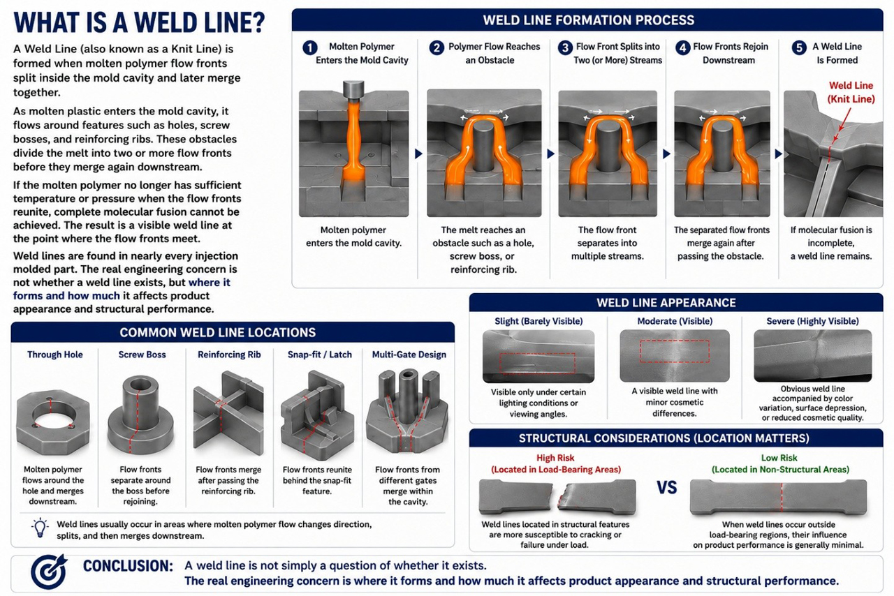
A weld line (also known as a knit line) is the line or interface formed when two or more molten polymer flow fronts separate and subsequently rejoin inside a mold cavity.
As molten plastic enters the cavity through the gate, it flows around obstacles such as through holes, screw bosses, reinforcing ribs, and other product features. These obstacles divide the melt into two or more flow fronts that travel around opposite sides before merging again downstream.
If the molten polymer retains sufficient temperature and pressure when the flow fronts reunite, the polymer chains can interdiffuse and bond together effectively, making the weld line almost invisible. However, if the melt has cooled significantly or pressure is insufficient, the polymer chains cannot fully fuse. Instead of forming a continuous molecular structure, the flow fronts simply meet at an interface, leaving behind a visible weld line and creating a localized reduction in mechanical strength.
Weld lines are present in nearly every injection molded component. The engineering challenge is not whether a weld line exists, but where it forms and how much it affects the product's appearance and structural performance.
Engineering Note
A weld line should not automatically be considered a molding defect. In most injection molded products, weld lines are a natural result of polymer flow. The key objective of mold engineering is to ensure they occur in locations where they do not compromise product functionality or cosmetic quality.
2. How Do Weld Lines Form?
When molten polymer flows through a mold cavity, it naturally follows the path of least resistance until it encounters a feature that interrupts its flow. Components such as through holes, screw bosses, reinforcing ribs, inserts, and other geometric features force the melt to divide into separate flow fronts before reuniting further downstream.
Whether these flow fronts fuse into a strong, nearly invisible joint—or leave behind a visible weld line—depends largely on the temperature, pressure, and molecular mobility of the polymer at the moment they meet. The weld line formation process can generally be divided into three stages.
- Stage 1 – Flow Separation
As molten polymer enters the mold cavity, it eventually reaches features that block its direct flow path. Typical examples include through holes, screw bosses, reinforcing ribs, inserts, and structural supports. Since the melt cannot pass through these obstacles, the advancing flow front splits into two or more streams that flow around opposite sides of the feature. At this stage, the polymer is still highly fluid, and the separated flow fronts continue filling the cavity independently. - Stage 2 – Independent Flow
After separation, each flow front travels along a different path around the obstacle. Although both streams originate from the same gate, they rarely experience identical molding conditions. Differences gradually develop in flow distance, cooling rate, pressure loss, shear conditions, and melt temperature. These differences become even more significant when the product has non-uniform wall thickness or asymmetric geometry. As the polymer cools, molecular mobility decreases; the longer the flow path, the greater the temperature loss before the melt fronts reunite. - Stage 3 – Flow Reunion
Once the separated flow fronts pass the obstruction, they meet again downstream. This is the critical stage in weld line formation. If the molten polymer still retains sufficient temperature and pressure, the polymer chains from both flow fronts diffuse across the interface and become entangled, forming a strong molecular bond. In many cases, the weld line becomes almost invisible and has little effect on mechanical performance. However, if the polymer has cooled excessively before the flow fronts meet, molecular mobility is significantly reduced. Instead of fully fusing together, the flow fronts simply contact one another, leaving behind a visible weld line with lower local strength than the surrounding material.
Why Some Weld Lines Are More Visible Than Others
Not all weld lines look the same. Some are only visible under certain lighting conditions, while others are accompanied by discoloration, shallow surface depressions, or noticeable cosmetic defects. Likewise, not every weld line has the same mechanical strength. The quality of a weld line is influenced by several factors, including:
- Melt temperature
- Mold temperature
- Injection speed
- Packing pressure
- Part wall thickness
- Gate location
- Number of gates
- Material properties
These variables work together to determine how effectively the polymer chains fuse when the flow fronts reunite. For this reason, weld line optimization should always consider the molding system as a whole rather than adjusting a single processing parameter independently.
Engineering Note
A weld line is not formed simply because two melt fronts meet. It forms because the two flow fronts fail to achieve complete molecular fusion at the point of convergence. Understanding this distinction helps engineers focus on improving polymer bonding rather than merely trying to hide the appearance of the weld line.
Key Takeaways
- Weld lines form when molten polymer separates and later rejoins inside the mold cavity.
- The quality of the weld line depends on the polymer's temperature, pressure, and molecular mobility when the flow fronts merge.
- Cooling, pressure loss, and flow path differences all influence weld line quality.
- Effective weld line control requires a combination of sound product design, mold design, and process optimization rather than a single corrective action.
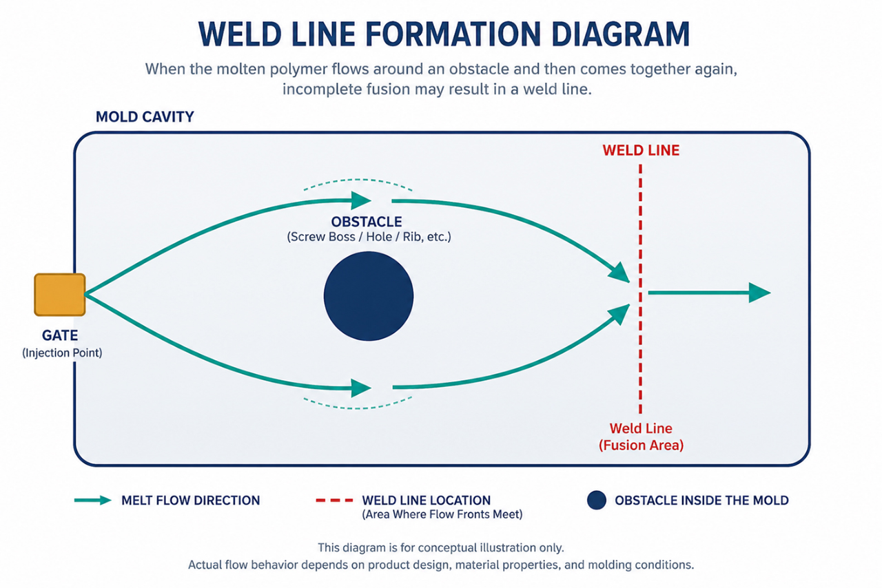 Molten polymer separates as it flows around an obstacle inside the mold cavity. After passing the obstruction, the flow fronts merge downstream. If fusion is incomplete due to insufficient temperature or pressure, a weld line is formed.
3. Where Do Weld Lines Commonly Occur?
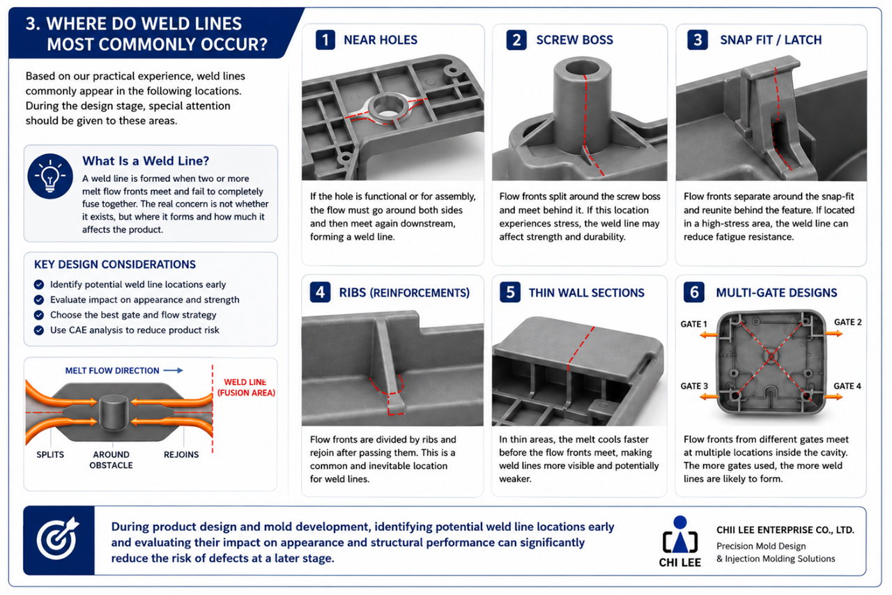
Although weld lines can form almost anywhere in an injection molded part, certain product features naturally create conditions that make weld line formation more likely. By recognizing these high-risk areas during the design stage, engineers can optimize gate placement, refine part geometry, and improve mold design before tooling is manufactured. The following locations deserve particular attention.
- Through holes: Through holes are one of the most common locations where weld lines occur. Whether the hole serves a functional, assembly, or ventilation purpose, molten polymer must flow around both sides before merging again downstream. As a result, a weld line almost always forms immediately behind the hole. If this region is subjected to mechanical loading during product use, engineers should evaluate whether the weld line could affect long-term durability.
- Screw bosses: Screw bosses interrupt polymer flow and create a natural separation of the melt front. Because screw bosses are typically used to secure product assemblies, they are often located in areas that experience repeated tightening forces and mechanical stress. If a weld line forms around the base of a screw boss, incomplete molecular bonding may reduce local strength and increase the likelihood of cracking during assembly or long-term service. For structural applications, weld lines around screw bosses should always be reviewed during the mold design stage.
- Snap-fit features: Snap-fit features are especially sensitive to weld lines. These components are designed to flex repeatedly during assembly and, in some cases, throughout the product's service life. If a weld line forms near the root of a snap-fit, where bending stress is greatest, fatigue resistance may be significantly reduced. Whenever possible, weld lines should be relocated away from primary bending regions by adjusting gate location or modifying the melt flow path.
- Reinforcing ribs: Reinforcing ribs improve part stiffness while minimizing material consumption. However, ribs also alter the direction of polymer flow. As molten polymer flows around adjacent ribs or reconnects where the rib joins the main wall, weld lines may develop along these junctions. Although these weld lines are often hidden from view, they should not be overlooked, especially when the ribs contribute to the product's structural performance.
- Thin-wall sections: Thin-wall sections cool much more rapidly than thicker regions. As the polymer loses heat, molecular mobility decreases before the separated flow fronts reunite. Consequently, weld lines formed in thin-wall areas tend to be more visible and may exhibit lower bonding strength than those formed in thicker sections. Maintaining consistent wall thickness throughout the part is one of the most effective ways to improve weld line quality.
- Multi-gate designs: Large or complex components often require multiple gates to achieve balanced cavity filling. While additional gates can reduce flow length and injection pressure, they also introduce multiple melt fronts that eventually converge. Each convergence point creates the potential for a weld line. In general, increasing the number of gates increases both the number and complexity of weld lines within the molded part. For this reason, gate quantity and gate location should always be evaluated through Mold Flow Analysis before finalizing the mold design.
Why Early Prediction Matters
One of the most effective ways to minimize weld line issues is to identify their likely locations before mold manufacturing begins. By combining Design for Manufacturability (DFM) principles with Mold Flow Analysis (CAE), engineers can predict where weld lines will form and determine whether those locations may affect:
- Product appearance
- Structural strength
- Assembly performance
- Long-term durability
If a weld line is expected to occur in a critical area, adjustments to the product design, gate location, or molding strategy can often be made before tooling is produced—saving both development time and manufacturing cost.
Engineering Note
A weld line is not inherently a design flaw. Its significance depends on where it forms and whether that location influences product performance. For this reason, experienced mold engineers focus on controlling the location of weld lines rather than attempting to eliminate them entirely.
Key Takeaways
- Through holes, screw bosses, snap-fits, ribs, and thin-wall sections are common weld line locations.
- Multi-gate designs naturally create additional weld lines where flow fronts converge.
- Early prediction using Mold Flow Analysis enables engineers to relocate weld lines before tooling is manufactured.
- The location of a weld line is often more important than its existence.
4. Do Weld Lines Always Reduce Part Strength?
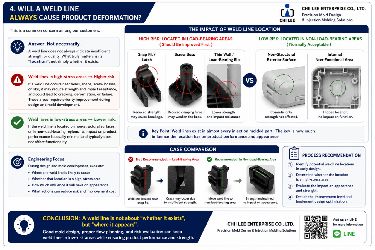
One of the most common misconceptions in plastic injection molding is that every weld line automatically indicates a weak or defective part. In reality, this is not always the case. A weld line does not necessarily reduce the overall strength of an injection molded component. Its actual impact depends on several factors, including the material, molding conditions, weld line quality, and—most importantly—its location within the part.
For engineers, the key question is not simply whether a weld line exists, but whether it forms in a region that experiences mechanical loading during the product's service life.
The Location Matters More Than the Weld Line Itself
Not every weld line requires corrective action. If a weld line forms on a cosmetic surface that experiences little or no mechanical stress, its influence on product performance is often negligible. In such cases, the primary concern is whether the weld line is visually acceptable to the customer.
However, the situation is very different when a weld line forms in a structural area. Locations such as screw bosses, snap-fit features, locking tabs, structural ribs, and thin load-bearing sections are designed to withstand assembly forces or repeated mechanical loading. If molecular bonding at the weld line is incomplete, these regions become more susceptible to crack initiation and fatigue failure over time. For this reason, weld lines located in structural features should always receive greater engineering attention than those found on cosmetic surfaces.
Cosmetic Weld Lines vs. Structural Weld Lines
From an engineering perspective, weld lines can generally be divided into two categories.
Cosmetic weld lines primarily affect the visual appearance of the molded part. Typical examples include exterior product surfaces, decorative covers, and consumer-facing components. Although they may be visible under certain lighting conditions, they usually have little influence on mechanical performance. The decision to improve these weld lines is typically based on customer appearance requirements rather than structural necessity.
Structural weld lines occur in regions that are subjected to mechanical loads during assembly or product operation. Typical examples include screw bosses, snap-fit roots, load-bearing brackets, and structural supports. If a weld line forms in these areas, incomplete molecular fusion may reduce tensile strength, impact resistance, and fatigue life. These weld lines should always be evaluated carefully during both product development and mold design.
How Weld Lines Affect Mechanical Performance
The degree to which a weld line influences part strength depends on how effectively the polymer chains fuse when the melt fronts merge. When processing conditions are optimized, the polymer chains from opposing flow fronts interlock to form a strong molecular bond. Under poor molding conditions, however, the interface between the two flow fronts remains weak. Possible consequences include:
- Reduced tensile strength
- Lower impact resistance
- Decreased fatigue life
- Earlier crack initiation
- Lower long-term durability
The severity of these effects varies depending on the polymer type, filler content, processing parameters, and part geometry.
Engineering Evaluation
Before deciding whether a weld line requires improvement, engineers should evaluate several key questions.
- Is the weld line located in a load-bearing area? If the answer is yes, further evaluation is recommended.
- Will the region experience repeated mechanical stress? Components subjected to repeated loading are more sensitive to localized reductions in strength.
- Is the weld line positioned on a visible cosmetic surface? If appearance is the primary concern, cosmetic improvement may be more important than structural optimization.
- Can the weld line be relocated? Adjusting the gate location or modifying the melt flow path often provides a more effective solution than attempting to eliminate the weld line entirely.
- Would Mold Flow Analysis provide additional insight? Simulation can predict weld line locations before tooling is manufactured, allowing engineers to optimize the design early in the development process.
Engineering Note
A weld line should be evaluated based on its function, not merely its appearance. An almost invisible weld line located in a highly stressed region may present a greater engineering concern than a clearly visible weld line on a non-structural cosmetic surface. For this reason, experienced engineers always consider both mechanical performance and appearance requirements before deciding whether corrective action is necessary.
Key Takeaways
- A weld line does not automatically indicate a weak part.
- The location of the weld line is often more important than its visibility.
- Structural weld lines require greater engineering attention than cosmetic weld lines.
- Material selection, molding conditions, and part design all influence weld line strength.
- Mold Flow Analysis helps engineers evaluate weld line performance before tooling is manufactured.
5. How to Reduce Weld Lines
Completely eliminating weld lines is rarely achievable in plastic injection molding. Instead, the primary engineering objective is to control where weld lines form, minimize their visibility, and ensure they do not compromise the product's appearance or structural performance. In practice, weld line optimization rarely depends on a single adjustment. The most effective results are usually achieved through a combination of product design improvements, mold design optimization, and scientific molding practices. The following are the seven most commonly used engineering approaches.
(1) Optimize Gate Location
Gate location has one of the greatest influences on weld line formation. Because the gate determines how molten polymer enters the mold cavity, changing its position can significantly alter melt flow patterns and relocate weld lines to less critical areas. Rather than attempting to eliminate a weld line, engineers often relocate it from a load-bearing feature to a non-structural or non-visible region. In many projects, optimizing gate location provides the greatest improvement while requiring the least modification to the mold.
Why it works: Changing the gate changes the flow path, and a different flow path changes where separate melt fronts meet. As a result, the weld line can often be moved away from areas where it would otherwise affect product quality.
- Best Applications
- Cosmetic components
- Structural parts
- Products with single-gate designs
- Components under development before tooling is finalized
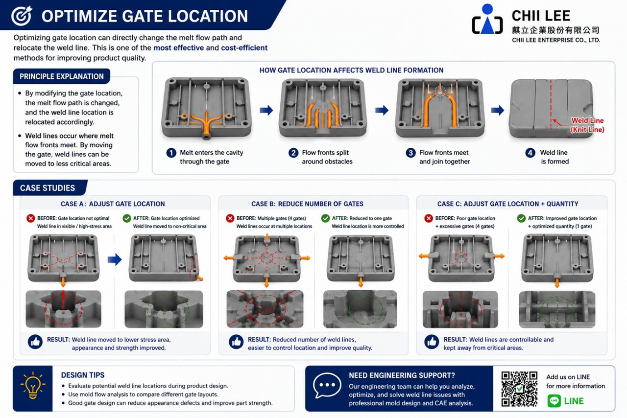
Figure 4. Optimizing Gate Location to Relocate Weld Lines — Adjusting the gate position changes melt flow patterns, allowing weld lines to form in less critical areas.
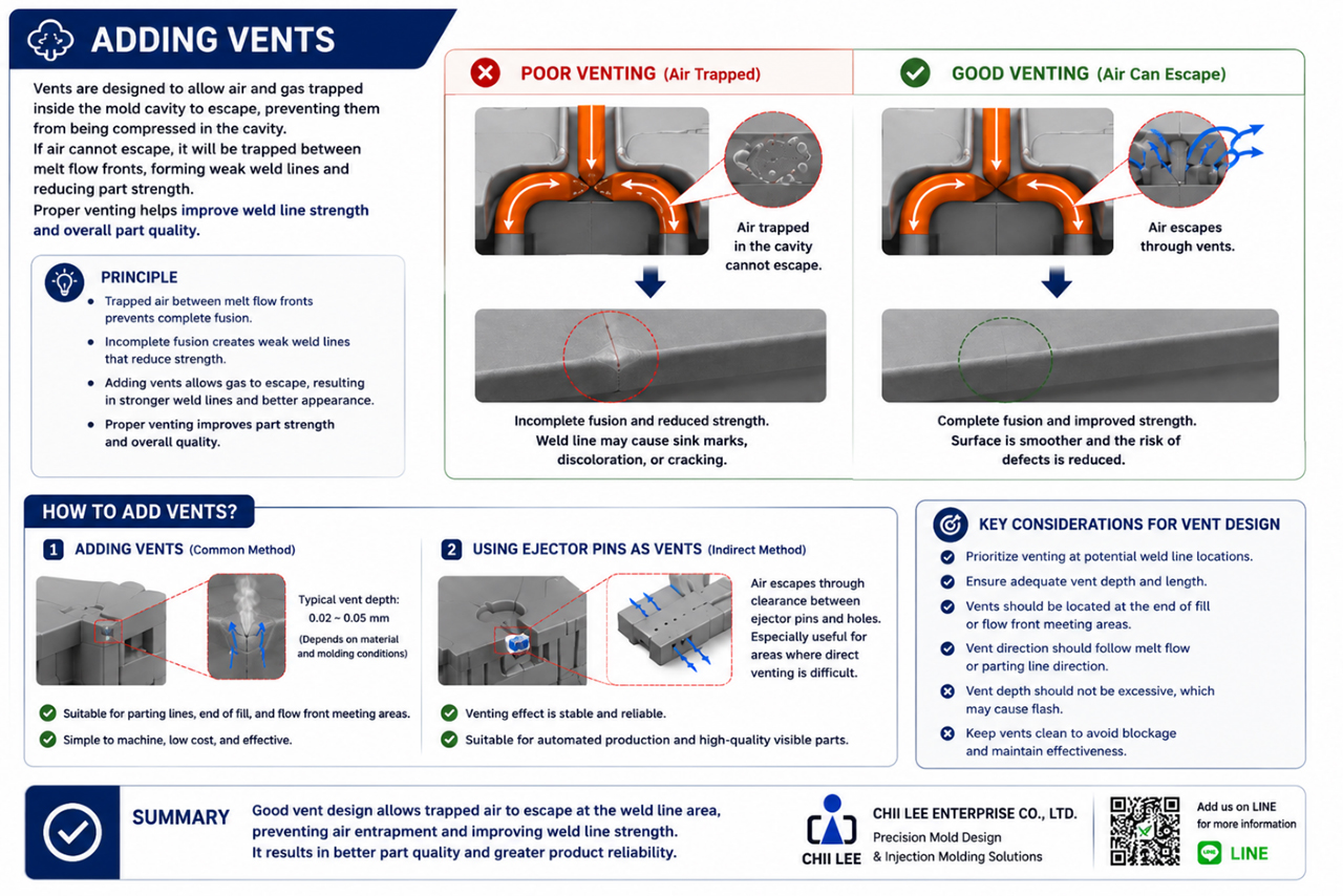
(2) Improve Mold Venting
Air is naturally trapped when two melt fronts converge. If this trapped air cannot escape efficiently, it becomes compressed between the two flow fronts, preventing complete molecular fusion. Poor venting may lead to more visible weld lines, burn marks, gas traps, and reduced weld line strength. Proper vent groove design allows air to escape before the melt fronts merge, improving both appearance and structural integrity.
Why it works: Good venting removes trapped air. Without trapped gas at the convergence point, opposing polymer flow fronts can fuse together more effectively.
Engineering tip: Before changing molding parameters, always verify that the mold provides adequate venting. Many weld line issues originate from poor venting rather than improper processing conditions.
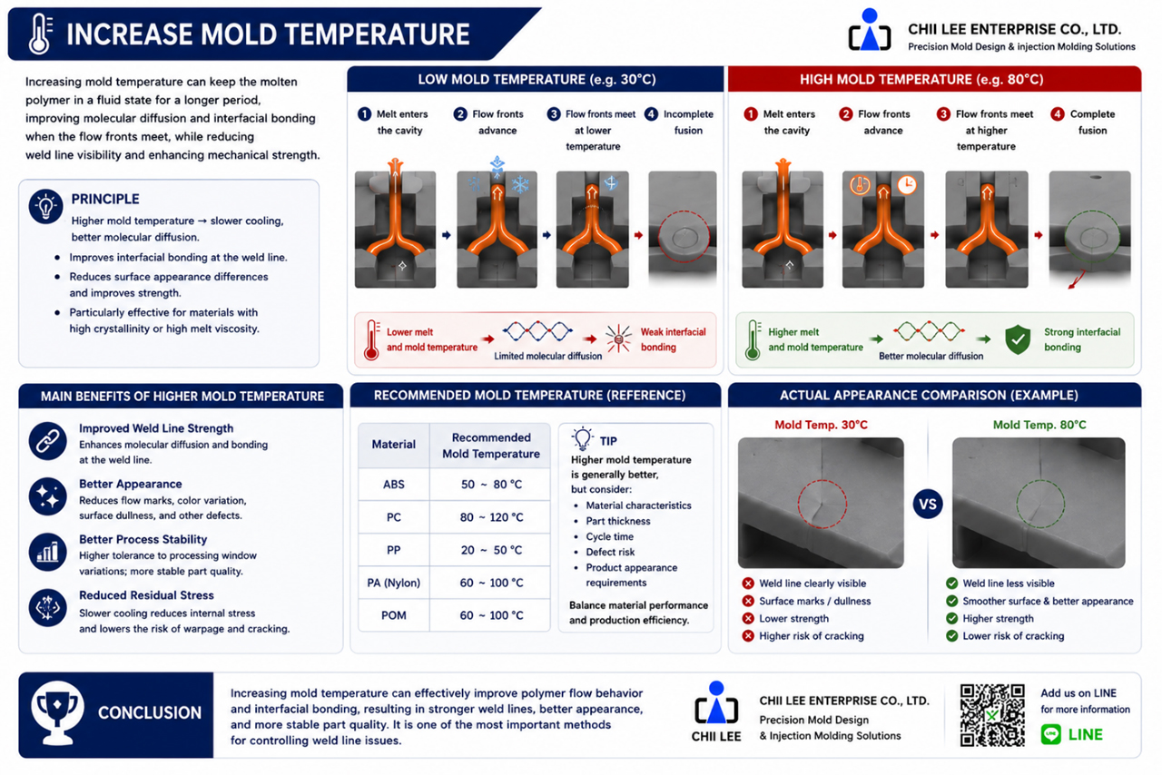
(3) Optimize Mold Temperature
Mold temperature plays an important role in weld line quality. A higher mold temperature slows the cooling rate of molten polymer, allowing the flow fronts to remain fluid for a longer period before merging. This increases molecular diffusion and improves weld line strength. However, excessively high mold temperatures may increase cycle time and reduce production efficiency. The objective is therefore to optimize, not simply maximize, mold temperature.
Benefits:
- Better molecular bonding
- Improved cosmetic appearance
- Reduced residual stress
- Stronger weld lines
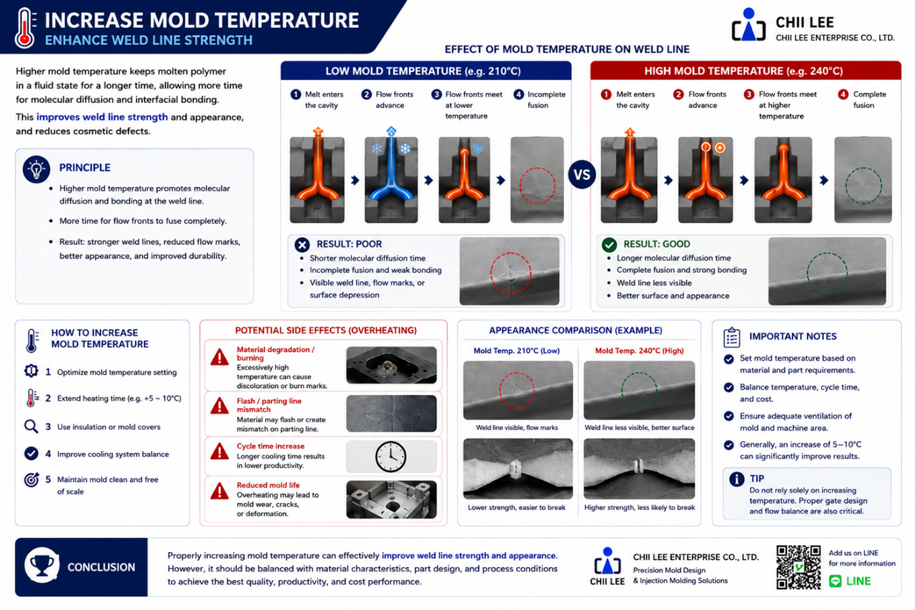
(4) Optimize Melt Temperature
Increasing melt temperature extends the time during which polymer chains remain mobile. When opposing flow fronts meet at a higher temperature, molecular diffusion becomes more effective, producing stronger weld lines. Processing temperatures should always remain within the material manufacturer's recommended processing window, since excessively high melt temperatures may cause material degradation, color variation, flash, and longer cooling times.
Why it works: Higher melt temperature allows polymer chains to interdiffuse more completely before solidification occurs.
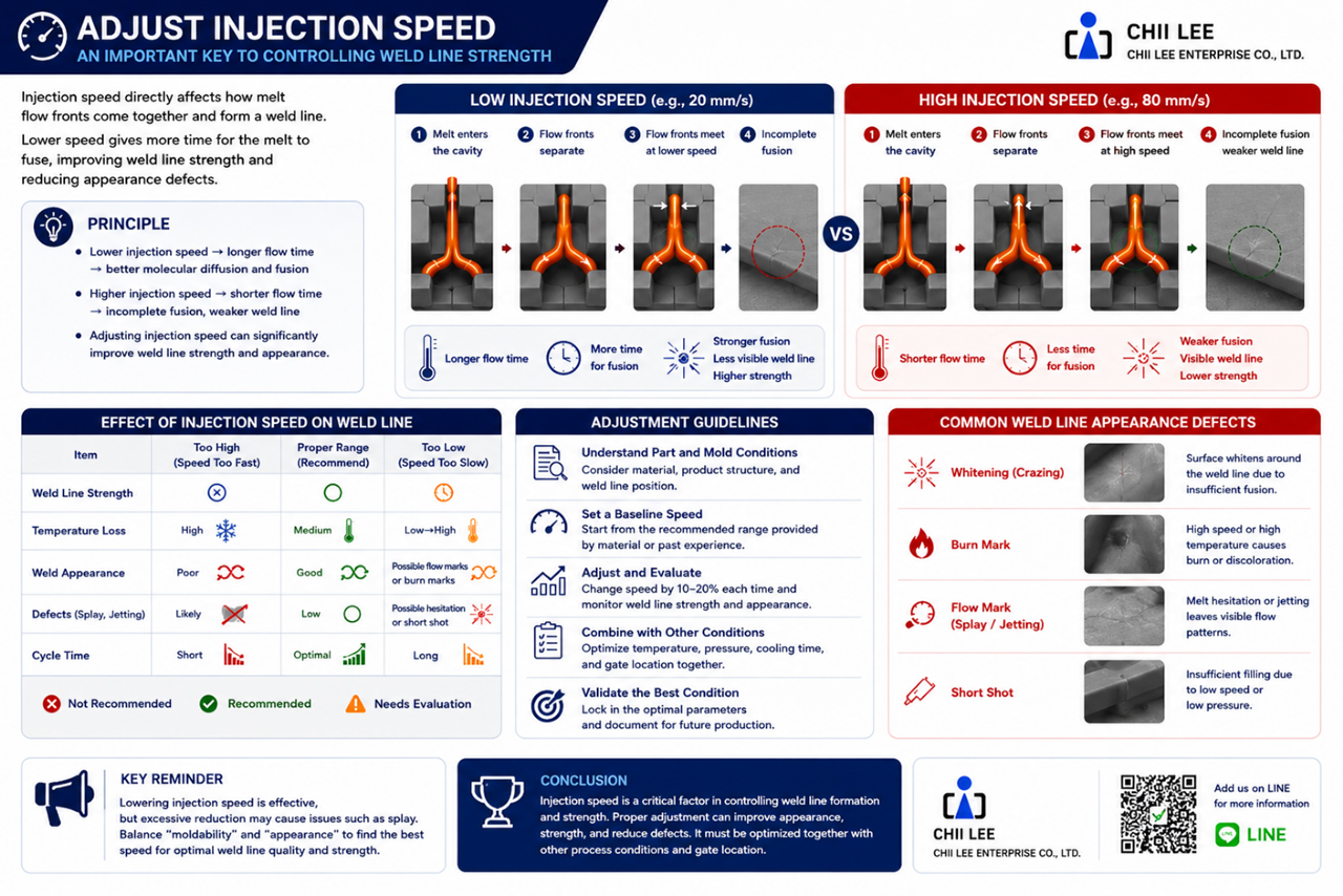
(5) Optimize Injection Speed
Injection speed directly affects how much heat the polymer retains while filling the mold cavity. A faster filling speed reduces heat loss before opposing flow fronts merge. It also increases local pressure and shear, improving molecular bonding at the weld line. However, excessive injection speed may introduce other molding defects such as jetting, flash, or burn marks. Injection speed should therefore be optimized together with other molding parameters rather than adjusted independently.
Engineering tip: Increasing injection speed is not always the answer. The best results are achieved by balancing injection speed with melt temperature, mold temperature, and packing pressure.
(6) Improve Product Design
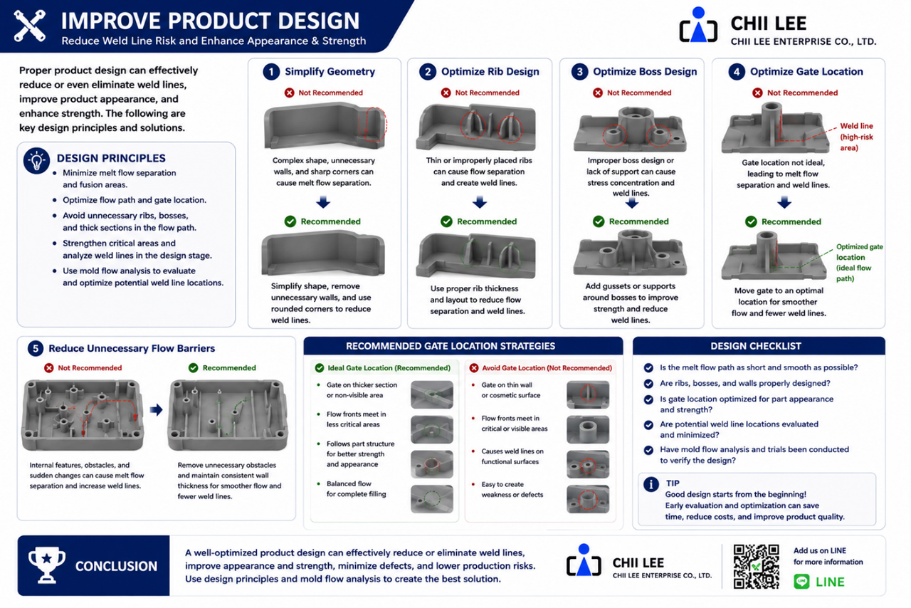
Some weld line issues cannot be solved by adjusting processing conditions alone. In such cases, product design should be reviewed.
Good design practices include:
- Maintaining uniform wall thickness
- Optimizing rib dimensions
- Relocating screw bosses
- Reducing unnecessary flow obstacles
- Avoiding excessive stress concentration
Addressing these issues during product development is generally far less expensive than modifying the mold after manufacturing.
Design tip: Whenever possible, design the product so that unavoidable weld lines occur in non-load-bearing and non-cosmetic regions.
(7) Perform Mold Flow Analysis (CAE)
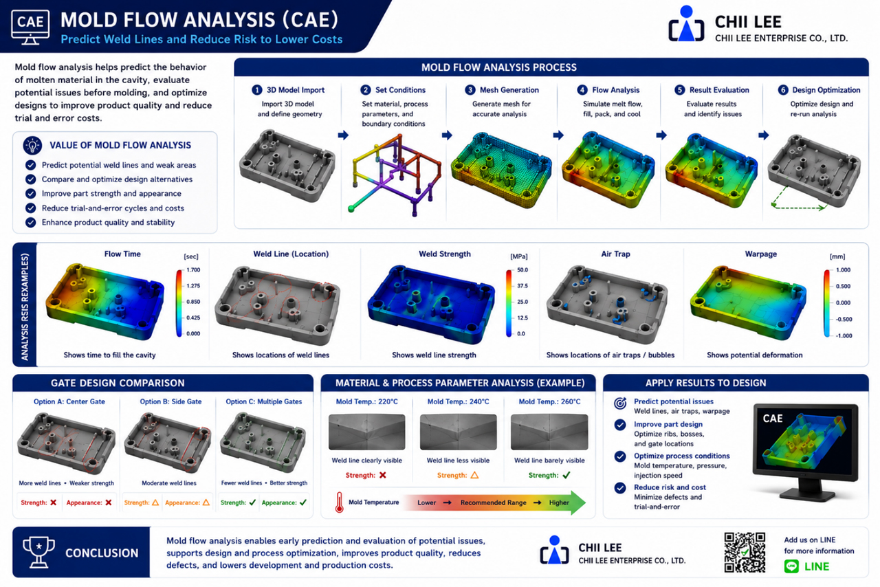
Mold Flow Analysis has become one of the most valuable engineering tools in modern mold development.
Before tooling is manufactured, simulation software can predict:
- Polymer flow patterns
- Weld line locations
- Air traps
- Pressure distribution
- Temperature distribution
- Filling balance
- Potential molding defects
By evaluating multiple gate layouts and molding conditions in a virtual environment, engineers can optimize the design before steel is cut.
This reduces development time, minimizes mold modifications, and improves the likelihood of achieving a stable production process.
CAE simulation predicts weld line formation before tooling is manufactured, allowing engineers to optimize gate design and processing conditions early in the development process.
Engineering Perspective
No single process parameter can completely eliminate weld lines. Successful weld line optimization requires engineers to evaluate the entire molding system, including product design, material selection, gate design, mold construction, processing conditions, and Mold Flow Analysis. The best solution is rarely the result of one adjustment alone. Instead, it comes from balancing all of these factors to achieve the optimal combination of appearance, structural performance, manufacturing efficiency, and production cost.
Engineering Note
Experienced mold engineers rarely ask, “Which process parameter should we change?” Instead, they ask, “What caused the weld line to form in this location?” Understanding the root cause leads to more effective and sustainable engineering solutions than simply adjusting machine settings through trial and error.
Key Takeaways
- Gate location is often the most influential factor affecting weld line location.
- Good venting improves molecular fusion by allowing trapped air to escape.
- Mold temperature and melt temperature work together to improve weld line quality.
- Injection speed should be optimized—not maximized.
- Product design is often the most cost-effective place to solve weld line issues.
- Mold Flow Analysis enables engineers to predict and optimize weld lines before tooling begins.
- The best results come from optimizing the entire molding system rather than a single parameter.
6. CHII LEE's Engineering Perspective
Over more than four decades of designing and manufacturing injection molds, CHII LEE has worked with customers across a wide range of industries, from consumer electronics and cosmetic packaging to industrial components and precision engineering applications. Throughout these projects, one principle has remained consistent: a successful mold is not one without weld lines—it is one in which weld lines are engineered to occur where they do not compromise product performance or appearance. This philosophy reflects how we approach every mold development project.
Weld Lines Are a Natural Result of Polymer Flow
Many customers initially assume that the presence of a weld line indicates poor mold quality. In reality, weld lines are an inherent characteristic of the injection molding process. Whenever molten polymer separates to flow around an obstacle and later reunites, a weld line is likely to form. Attempting to eliminate every weld line is often impractical and may require unnecessary increases in tooling complexity, production cost, or cycle time. Rather than pursuing a “zero weld line” objective, experienced mold engineers focus on understanding polymer flow behavior and controlling where weld lines occur.
Engineering Begins Before Tooling Is Manufactured
The most effective weld line solution is rarely found on the molding machine. Instead, it begins during product development. Before mold manufacturing starts, our engineering team carefully reviews:
- Product geometry
- Wall thickness distribution
- Rib and screw boss design
- Gate location
- Runner layout
- Mold venting strategy
- Material characteristics
This Design for Manufacturability (DFM) review helps identify potential weld line concerns before they become manufacturing problems.
Using Mold Flow Analysis to Predict Weld Lines
For products with complex geometry or demanding quality requirements, Mold Flow Analysis (CAE) provides valuable insight before tooling is manufactured. Simulation enables engineers to predict:
- Polymer flow patterns
- Weld line locations
- Air traps
- Pressure distribution
- Temperature distribution
- Filling balance
These results allow design adjustments to be evaluated digitally, reducing trial-and-error during mold qualification and minimizing costly tooling revisions.
Balancing Appearance, Strength, and Manufacturing Efficiency
Every injection molded product involves engineering trade-offs. For example, relocating a weld line may improve cosmetic appearance but require a more complex runner system; increasing mold temperature may strengthen the weld line but extend cycle time; adding additional gates may shorten the flow length while introducing new weld lines elsewhere. Because every design decision influences other aspects of the molding process, successful engineering requires balancing multiple objectives rather than optimizing a single parameter.
At CHII LEE, we evaluate each project from a complete engineering perspective to achieve the best balance among:
- Product appearance
- Mechanical performance
- Manufacturing stability
- Tooling complexity
- Production efficiency
- Overall project cost
Engineering Is About Managing Risk
From our experience, weld lines become problematic only when they appear in the wrong location. If a weld line forms in a highly stressed structural feature or on a critical cosmetic surface, corrective action is usually justified. However, if the weld line occurs in a non-visible and non-load-bearing region, additional tooling modifications may provide little practical benefit while increasing project cost. Successful mold engineering is therefore not about eliminating every weld line—it is about making informed engineering decisions based on function, manufacturability, and cost.
Successful weld line management considers product design, mold design, material behavior, processing conditions, and Mold Flow Analysis together rather than evaluating any single factor independently.
Engineering Note
The best engineering solution is not always the one that produces the least visible weld line. The best solution is the one that delivers the optimum balance between product quality, manufacturing stability, tooling cost, and long-term reliability.
Key Takeaways
- Weld lines are a natural result of polymer flow during injection molding.
- Engineering efforts should focus on controlling weld line location rather than eliminating weld lines completely.
- Early DFM review and Mold Flow Analysis reduce development risk before tooling begins.
- Successful mold engineering balances appearance, strength, manufacturability, and production cost.
- Every weld line should be evaluated according to its functional significance rather than appearance alone.
Frequently Asked Questions (FAQ)
Q: Can weld lines be completely eliminated?
A: In most injection molded products, the answer is no. Weld lines are a natural consequence of molten polymer flow separating and rejoining inside the mold cavity. As long as the product geometry causes the melt to flow around features such as holes, ribs, screw bosses, or inserts, weld lines are likely to form. However, by optimizing product design, gate location, molding conditions, and Mold Flow Analysis, engineers can significantly reduce their visibility and minimize their effect on mechanical performance. The engineering objective is not to eliminate every weld line, but to ensure that any remaining weld lines do not affect product function, appearance, or long-term reliability.
Q: Are weld lines the same as flow marks?
A: No. Although both are common injection molding defects, they are caused by different mechanisms. A weld line is created when two or more molten polymer flow fronts merge after being separated by an obstacle. A flow mark, on the other hand, is caused by changes in melt flow velocity, cooling behavior, or surface solidification during cavity filling. Because the root causes are different, the corrective actions are also different. Correctly identifying the defect is always the first step toward selecting an effective solution.
Q: Are weld lines always visible?
A: Not necessarily. The appearance of a weld line depends on several factors, including polymer type, colorant concentration, glass fiber or mineral fillers, surface texture, mold finish, painting or coating processes, and molding conditions. Under certain material and processing combinations, weld lines may be almost invisible. However, even when they cannot be seen, they may still influence mechanical performance if they are located in a highly stressed region. For critical applications, engineering evaluation should rely on Mold Flow Analysis and mechanical testing rather than visual inspection alone.
Q: Does every weld line require mold modification?
A: No. Many weld line concerns can first be improved through process optimization. Typical adjustments include melt temperature, mold temperature, injection speed, packing pressure, and mold venting. Only when these improvements are insufficient should engineers consider modifying the gate location, product geometry, or mold design. Whether tooling modifications are necessary ultimately depends on the weld line's location and its actual impact on appearance, structural performance, and product function.
Engineering Note
The presence of a weld line does not automatically indicate a defective mold. Every weld line should be evaluated based on its location, function, and engineering significance rather than appearance alone.
Conclusion
Weld lines are an inherent characteristic of the plastic injection molding process. They are not necessarily manufacturing defects, nor do they automatically indicate poor mold quality. By understanding how weld lines form, predicting where they are likely to occur, and applying sound engineering principles during product design, mold development, and process optimization, manufacturers can effectively control their impact on both product appearance and mechanical performance.
Successful injection molding is not about eliminating every weld line. It is about understanding polymer flow, making informed engineering decisions, and ensuring that weld lines occur where they have little or no influence on product quality. With the support of Design for Manufacturability (DFM), Mold Flow Analysis (CAE), optimized mold design, and scientific molding practices, weld lines become a predictable and manageable aspect of the injection molding process rather than a costly production problem.
Need Assistance Evaluating Your Product?
If your injection molded products are experiencing cosmetic concerns, insufficient strength, or production challenges related to weld lines, CHII LEE is here to help. Our engineering team provides comprehensive technical support, including:
- Mold Flow Analysis (CAE)
- Design for Manufacturability (DFM) Review
- Injection Mold Design
- Product Design Optimization
- Scientific Molding Process Optimization
- Production Troubleshooting
By combining decades of practical experience with engineering-driven solutions, we help customers improve product quality, reduce tooling revisions, and achieve stable, cost-effective mass production.
Contact CHII LEE
Email: fan@chiilee.com
Tel: +886-4-25272790 Ext. 12
Cell phone: +886-972-364510
Website: www.chiilee.com