


FAQ

- FAQ

Frequently asked questions
-
Q2025-08-27Custom Cable Marker Rings|Durable POM Material for High-Efficiency Projects Open or CloseA
1. Why Custom Cable Marker Rings Are Essential
In modern engineering, data center operations, and public infrastructure projects, clear and durable cable identification is indispensable. Incorrect cable connections can cause equipment downtime, data loss, or even safety hazards.
For low-voltage engineering companies, system integrators, IT maintenance teams, and automation equipment manufacturers, Custom Cable Marker Rings—also known as Cable Identification Rings or Cable Coding Rings—provide immediate cable recognition, reducing wiring errors and maintenance delays while meeting engineering acceptance standards.
Compared to traditional adhesive cable labels, Cable Marker Rings offer greater durability and can be customized in size, color, and text coding according to project requirements. They are suitable for both indoor server rooms and harsh outdoor environments, making them an efficient cable management solution for professionals.2. Main Application Scenarios
1. Low-Voltage Engineering & System Integration
Used in network and communication wiring for office buildings, hospitals, schools, and shopping malls. Color coding and text engraving make installation and maintenance more accurate.2. IT & Data Center Operations
In data centers and server racks, marker rings allow quick location of specific cables, reducing troubleshooting time and minimizing network downtime.3. Automation Equipment Manufacturing
Inside machinery, cables can be identified instantly using Cable ID Rings or Cable Tag Clips, reducing production downtime during maintenance.4. Telecommunications & Public Works
Suitable for indoor and outdoor cables, fiber optics, and switchboards. Weather-resistant materials withstand high temperatures, humidity, and chemical corrosion.5. International Consumables Distribution
C-Type Cable Marker Rings can be produced to meet various market demands, including specific colors, languages, and standards—ideal for global distributors who require compliance with local regulations.3. Core Features & Functions
- Multiple Sizes Available: Fits various cable diameters (e.g., CAT5, CAT6, fiber optic), ensuring compatibility for diverse applications.
- Color Coding: Can follow international standards (TIA/EIA-606) or custom project color schemes for intuitive cable identification systems.
- Text & Code Printing: Options for laser engraving or ink printing with wear-resistant, clear markings for long-term readability.
- Durable POM (Polyoxymethylene) Material: Manufactured from high-performance POM engineering plastic, offering excellent resistance to high temperatures, acids, alkalis, abrasion, and impact. Its low moisture absorption and high dimensional stability ensure a secure fit and long-lasting clarity, significantly reducing replacement frequency and maintenance costs.
- C-Type Flexible Opening Design: Can be quickly installed even after wiring is complete—no need to disconnect cables, saving installation time.
- Low MOQ & Fast Delivery: Flexible order quantities for both large and small projects; urgent orders can be fulfilled promptly to meet deadlines.
4. Key Advantages
- Reduce Wiring Errors: Clear labeling minimizes misconnection and maintenance mistakes.
- Boost Installation & Maintenance Efficiency: Speeds up cable identification and troubleshooting.
- Meet Inspection Standards: Standardized labeling ensures smooth project acceptance.
- Enhance Professional Image: Neat and consistent cable identification accessories reinforce client confidence.
- Extend Product Lifespan: Durable materials reduce replacement frequency and consumable costs.
- POM Reliability: POM's superior resistance to temperature, chemicals, abrasion, and impact ensures Custom Cable Marker Rings remain legible and securely attached in demanding environments.
5. Conclusion & Purchasing Tips
For contractors, IT teams, telecom operators, and public works departments, Custom Cable Marker Rings are more than labeling tools—they are essential for minimizing operational risks and improving project efficiency.
When choosing a supplier, prioritize:
- Flexible Low MOQ capability
- Comprehensive customization services
- Fast delivery & international shipping experience
- ISO certification & strict quality control
With over 40 years of experience in plastic product manufacturing, CHII LEE Enterprise Co., Ltd. delivers high-quality, durable, and customizable Cable Marker Rings, Cable Identification Rings, and Cable Coding Rings to clients worldwide—helping you achieve efficient, safe, and professional cable management for any project.
FAQ
Q1: What is the minimum order quantity for Custom Cable Marker Rings?
A: CHII LEE offers low MOQ options, allowing small-batch customization with quick production.Q2: Will the marker rings fade or get damaged quickly in outdoor use?
A: Made from high-performance POM material, they undergo weather-resistance testing to ensure long-term durability.Q3: Can I print my company logo or project code on the rings?
A: Yes, we provide laser engraving and printing options for brand recognition and project management.Get Your Custom Cable Marker Ring Solution Today
Email: service@chiilee.com
Tel: +886-4-25272790 / WhatsApp: +886 972-364510
Website: https://www.chiilee.com/en/ -
Q2025-09-01Improving Cable Management Efficiency – Industrial Applications of POM Heat & Chemical Resistant CabOpen or CloseA
Introduction
In demanding industrial environments, the clarity and durability of cable identification directly affect equipment operation efficiency and maintenance safety. Traditional cable tags or generic plastic cable identification clips often fail to remain stable under high temperatures, exposure to acids/alkalis, oil contamination, or harsh outdoor weather, resulting in faded or detached labels that increase maintenance risks and costs.
CHII LEE understands the high requirements of various industries for industrial cable identification solutions. We manufacture our POM Heat & Chemical Resistant Cable Marker (also known as Cable ID Ring, Cable Identification Ring, Cable Coding Ring) using premium-grade POM (Polyoxymethylene). With its superior heat resistance, chemical resistance, and mechanical strength, it provides a long-lasting and reliable cable management tool for chemical plants, energy facilities, telecommunications, transportation, and automation equipment industries.Technical Advantages
CHII LEE’s premium POM Cable Marker offers the following technical advantages:
- High weather resistance & long service life
Withstands prolonged exposure to UV sunlight, rain, and extreme temperature fluctuations. Outlasts conventional cable markers, reducing replacement frequency and maintenance costs. - Excellent heat & chemical resistance
Endures continuous operation in environments up to 100°C and resists acids, alkalis, oils, and most industrial solvents—ideal for chemical plants, industrial power distribution marking, and high-temperature processes. - High mechanical strength & deformation resistance
Even when clamped on cables for extended periods, the Cable Identification Ring maintains a secure fit without loosening or warping due to external force or temperature changes. - Multiple sizes & color options
Available in various inner diameters and colors for easy classification by cable size and function, compliant with international color coding standards (e.g., TIA/EIA-606), enhancing the efficiency of any cable identification system. - Custom engraving & laser marking
Supports printing or laser engraving of project codes, equipment names, or company logos. Scratch-resistant and wear-resistant for long-term readability. - C-shaped flexible opening design
As a professional C-type Cable Marker, it can be installed without disconnecting the cable—ideal for post-installation labeling or quick replacement during maintenance.
Industrial Application Case 1: Chemical Plants & Process Equipment
Chemical production environments are often accompanied by high-temperature pipelines, corrosive gases, and acidic/alkaline liquids, demanding highly durable identification materials.
One chemical plant fully adopted CHII LEE’s POM Heat & Chemical Resistant Cable Marker in its control systems and power cables. Using color-coded and engraved markers to differentiate functions, the labeling remained intact and clear after years of operation. Maintenance staff could quickly locate cables, improving efficiency by 40% and significantly reducing downtime caused by miswiring.Industrial Application Case 2: Outdoor Energy & Public Infrastructure
In power companies, port facilities, and transportation infrastructure, cables are exposed to prolonged sunlight, rain, salt spray, and dust. Traditional PVC Cable Coding Rings often become brittle and fade over time.
A coastal substation replaced its PVC tags with CHII LEE’s POM Cable ID Rings. The service life of the new markers extended from 2–3 years to over 5 years, and even after typhoons and high-humidity conditions, the markings remained clear and legible—dramatically reducing replacement frequency, lowering maintenance costs, and improving onsite safety.Frequently Asked Questions (FAQ)
Q1: What is the maximum temperature that a POM cable marker can withstand?
A1: In general, it can withstand continuous exposure up to 100°C, and higher temperatures for short periods. Exact data may vary depending on the material formulation.Q2: Will the laser-engraved text fade over time?
A2: No. The surface of POM is scratch- and wear-resistant after laser engraving, ensuring long-term readability.Q3: Is it suitable for long-term outdoor use?
A3: Yes. POM material has UV resistance and excellent weatherability, making it suitable for prolonged outdoor applications.Q4: Can it be customized in small quantities?
A4: Yes. CHII LEE offers flexible low-MOQ orders, with customization available from as few as a few hundred pieces.Conclusion
Whether in the high-temperature, corrosive environment of a chemical plant or the sun-exposed, weather-beaten conditions of outdoor energy and public infrastructure, CHII LEE’s POM Heat & Chemical Resistant Cable Marker (also known as Cable Identification Ring, Cable ID Ring) delivers long-lasting, stable cable identification.
Our products combine durability, flexibility, and customization, supporting low MOQ orders and fast delivery—ensuring your projects are managed efficiently, safely, and professionally.
Contact CHII LEE today to get your customized POM Cable Marker solution and achieve worry-free cable management! - High weather resistance & long service life
-
Q2025-09-08Cooperation & Process TransparencyOpen or CloseA
Q1: How long does it take from quotation to sample?
A: The process usually takes about 45 days, including mold design, tooling, and sampling.Q2: What information is required to start development?
A: You can provide either 2D drawings, 3D files, or a physical sample—any one of the three works.Q3: How is communication and project follow-up handled?
A: Each project is assigned a dedicated account manager, with English and multilingual support for smooth global collaboration.Q4: How many revisions are allowed for samples? Are there extra charges?
A: If production follows the provided drawings, no modification fees are charged during sampling.
However, if design changes are requested after mold completion, additional tooling costs will apply. -
Q2025-09-19Improving Cable Management Efficiency – Industrial Applications of POM Heat & Chemical Resistant CabOpen or CloseA
Introduction
In demanding industrial environments, the clarity and durability of cable identification directly affect equipment operation efficiency and maintenance safety. Traditional cable tags or generic plastic cable identification clips often fail to remain stable under high temperatures, exposure to acids/alkalis, oil contamination, or harsh outdoor weather, resulting in faded or detached labels that increase maintenance risks and costs.
CHII LEE understands the high requirements of various industries for industrial cable identification solutions. We manufacture our POM Heat & Chemical Resistant Cable Marker (also known as Cable ID Ring, Cable Identification Ring, Cable Coding Ring) using premium-grade POM (Polyoxymethylene). With its superior heat resistance, chemical resistance, and mechanical strength, it provides a long-lasting and reliable cable management tool for chemical plants, energy facilities, telecommunications, transportation, and automation equipment industries.Technical Advantages
CHII LEE's premium POM Cable Marker offers the following technical advantages:
- High weather resistance & long service life
Withstands prolonged exposure to UV sunlight, rain, and extreme temperature fluctuations. Outlasts conventional cable markers, reducing replacement frequency and maintenance costs. - Excellent heat & chemical resistance
Endures continuous operation in environments up to 100°C and resists acids, alkalis, oils, and most industrial solvents—ideal for chemical plants, industrial power distribution marking, and high-temperature processes. - High mechanical strength & deformation resistance
Even when clamped on cables for extended periods, the Cable Identification Ring maintains a secure fit without loosening or warping due to external force or temperature changes. - Multiple sizes & color options
Available in various inner diameters and colors for easy classification by cable size and function, compliant with international color coding standards (e.g., TIA/EIA-606), enhancing the efficiency of any cable identification system. - Custom engraving & laser marking
Supports printing or laser engraving of project codes, equipment names, or company logos. Scratch-resistant and wear-resistant for long-term readability. - C-shaped flexible opening design
As a professional C-type Cable Marker, it can be installed without disconnecting the cable—ideal for post-installation labeling or quick replacement during maintenance.
Industrial Application Case 1: Chemical Plants & Process Equipment
Chemical production environments are often accompanied by high-temperature pipelines, corrosive gases, and acidic/alkaline liquids, demanding highly durable identification materials.
One chemical plant fully adopted CHII LEE's POM Heat & Chemical Resistant Cable Marker in its control systems and power cables. Using color-coded and engraved markers to differentiate functions, the labeling remained intact and clear after years of operation. Maintenance staff could quickly locate cables, improving efficiency by 40% and significantly reducing downtime caused by miswiring.Industrial Application Case 2: Outdoor Energy & Public Infrastructure
In power companies, port facilities, and transportation infrastructure, cables are exposed to prolonged sunlight, rain, salt spray, and dust. Traditional PVC Cable Coding Rings often become brittle and fade over time.
A coastal substation replaced its PVC tags with CHII LEE's POM Cable ID Rings. The service life of the new markers extended from 2–3 years to over 5 years, and even after typhoons and high-humidity conditions, the markings remained clear and legible—dramatically reducing replacement frequency, lowering maintenance costs, and improving onsite safety.Frequently Asked Questions (FAQ)
Q1: What is the maximum temperature resistance of POM cable markers?
A1: They can generally withstand continuous use from -20℃ to 100℃, and can endure higher temperatures for short periods. The exact data depends on the material formulation.Q2: Will the laser-engraved text fade over time?
A2: No. The surface of POM is scratch- and wear-resistant after laser engraving, ensuring long-term readability.Q3: Is it suitable for long-term outdoor use?
A3: Yes. POM material has UV resistance and excellent weatherability, making it suitable for prolonged outdoor applications.Q4: Can it be customized in small quantities?A4: Yes. CHII LEE offers flexible low-MOQ orders, with customization available from as few as a few hundred pieces.
Conclusion
Whether in the high-temperature, corrosive environment of a chemical plant or the sun-exposed, weather-beaten conditions of outdoor energy and public infrastructure, CHII LEE's POM Heat & Chemical Resistant Cable Marker (also known as Cable Identification Ring, Cable ID Ring) delivers long-lasting, stable cable identification.
Our products combine durability, flexibility, and customization, supporting low MOQ orders and fast delivery—ensuring your projects are managed efficiently, safely, and professionally.📞 Contact CHII LEE today to get your customized POM Cable Marker solution and achieve worry-free cable management!
- High weather resistance & long service life
-
Q2026-03-19How to Design with Weld Lines in Mind from the Start?Open or CloseA
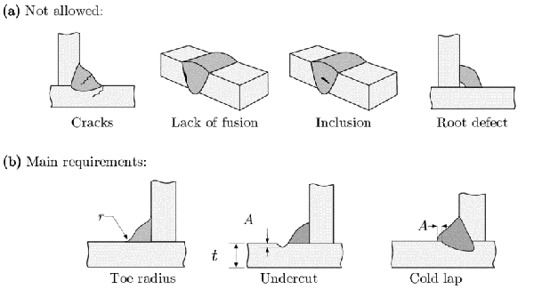
Weld lines are not defects that should only be addressed after injection molding—they are predictable outcomes that can be managed during the design phase.
This article explains how to strategically guide weld line locations early in product development, helping to avoid costly corrections later in tooling or production.Why Are Weld Lines Often Discovered Too Late?
In many projects, weld lines are only identified during mold trials or early production stages.
At that point, the product design and structure are already finalized, leaving only limited options for adjustment:- Minor tuning of injection parameters
- Limited modification of gate and runner systems
- Surface finishing or cosmetic correction
However, these solutions typically only improve the issue—they rarely eliminate the root cause.
Weld lines are not unexpected defects. They are the direct result of decisions made during the design stage.
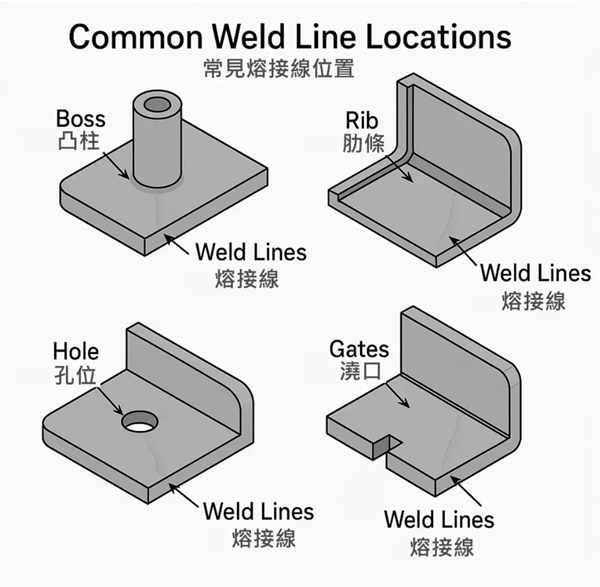
What Design Features Commonly Lead to Weld Lines?
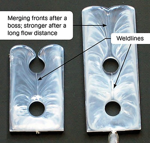
In injection molding, whenever molten plastic flow is divided and then recombines, weld lines are almost inevitable.
The following design features are the most common contributors:- Holes (screw bosses, through-holes, ventilation holes)
- Inserts or window/opening structures
- Significant wall thickness variation
- Symmetrical geometries with single-direction gating
These features are not inherently problematic. However, without considering melt flow behavior during design, weld lines may appear in undesirable locations.
How Can Designers “Control” Weld Line Locations?
Advanced injection molding design does not aim to eliminate weld lines entirely—it aims to control where they occur.1. Keep Weld Lines Away from Critical Stress Areas
During the design phase, evaluate load paths and avoid placing weld lines in:- High stress concentration zones
- Areas subject to repeated mechanical fatigue
- Structural regions critical for load-bearing after assembly
By aligning part geometry with flow direction, weld lines can be guided to low-impact areas.
2. Integrate Weld Lines into Surface Design
For cosmetic parts, weld lines do not always need to be removed—they can be visually managed:
- Align with decorative lines or parting lines
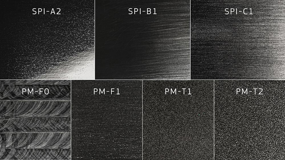
- Match surface texture direction with flow direction
- Use matte finishes or fine textures to reduce visual contrast
This approach is often more stable and consistent than post-processing methods such as polishing or coating.
3. Hide Weld Lines Through Assembly Design
For multi-component products, weld lines can be strategically positioned in:
- Non-visible surfaces after assembly
- Areas covered by other components
This allows functional integrity to be maintained while minimizing visual impact.
The Earlier You Address Weld Lines, the Lower the CostFrom a project management perspective, the timing of weld line considerations directly impacts cost and risk:
- Design stage adjustments: Minimal to no additional cost
- Post-trial modifications: Mold rework and schedule delays
- Post-production fixes: Increased quality risks and delivery pressure
The most effective solution for weld lines is never at the final stage—it is at the beginning.
Conclusion: Weld Lines as a Shared Language Between Design and Engineering
Weld lines are not merely a molding issue.
They are the result of the interaction between:- Product design
- Material behavior
- Mold structure
- Processing conditions
When weld lines are anticipated and strategically planned during the early design phase, injection molding simply becomes the process that reliably executes the correct engineering decisions.
-
Q2026-03-19Are Weld Lines in Plastic Injection Molding Always Required to Be Eliminated?Open or CloseA
— Rethinking from Design and Structural Perspectives
In our previous article, we explained what weld lines are, why they occur, and common approaches to improving them.
However, in real-world engineering practice, a more critical yet often overlooked question is: Do all weld lines truly need to be eliminated?
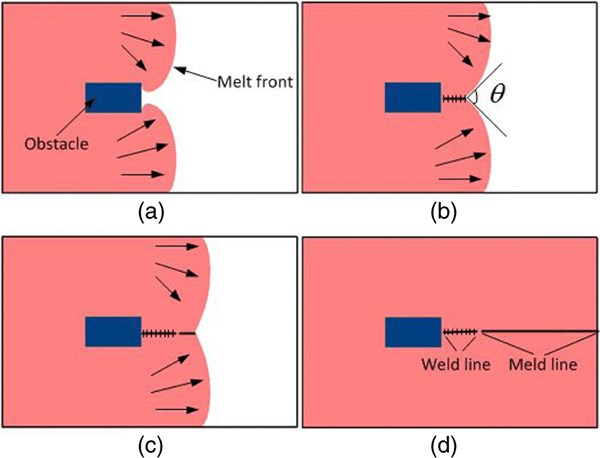
The answer is: Not necessarily.Not All Weld Lines Are Defects
In injection molding, weld lines are a natural result of molten plastic flow behavior.
Whenever there are flow splits, obstacles, holes, or inserts, weld lines are almost inevitable.
The real engineering concern is not whether a weld line exists, but rather:- Where the weld line is located
- Whether it affects structural integrity, safety, or function
- Whether it meets the actual requirements of the product
In some cases, overemphasizing the elimination of weld lines may even introduce new risks.
How Engineers Evaluate Whether a Weld Line Is Acceptable
In practice, engineers typically assess weld lines based on three key factors:
1. Location of the Weld Line
The impact of a weld line is highly dependent on where it appears:- Is it located in a load-bearing area?
- Is it on a critical assembly surface?
- Is it on a surface with high aesthetic requirements?
If a weld line appears in a non-load-bearing area, away from critical assembly zones, and does not affect appearance, it is often structurally acceptable.
2. Actual Application of the Product
Different products have vastly different tolerances for weld lines:
- Decorative parts vs. structural components
- Disposable products vs. long-term use products
- Requirements for waterproofing, sealing, or impact resistance
For example, cosmetic or visible parts may be highly sensitive to even minor weld lines, while internal structural components prioritize strength and dimensional stability.
3. Material Characteristics
Material properties often determine how much weld lines can be improved:
- Glass fiber or mineral-filled materials naturally tend to show more visible weld lines
- High-flow materials improve fusion but may compromise strength
- High-strength materials are often more sensitive to temperature and shear conditions
These factors significantly influence engineering decisions, rather than simply pursuing visual perfection.
Why "Forcing" Weld Line Elimination Can Be Counterproductive
In practice, there are many cases where attempting to eliminate weld lines creates new problems:
- Changing gate location → leading to uneven filling or warpage
- Increasing melt temperature → causing silver streaks, burning, or material degradation
- Raising injection pressure → increasing mold stress and reduces tool life
- Adding surface treatments → increasing costs and extending lead time
Engineering is not about choosing what looks best— it is about choosing what works best.
A Mature Approach: Anticipate Weld Lines During Design
A well-developed injection molding design does not rely on post-process corrections.
Instead, it considers weld lines from the very beginning:- How the melt flow will split and converge
- Whether weld lines can be guided to non-critical areas
- Whether structural features or surface textures can help minimize visual impact
Good injection molding design is not about eliminating weld lines— it is about placing them in the right locations.
Conclusion
Weld lines are not a problem that can be solved by adjusting a single parameter. They require a comprehensive engineering evaluation involving design, material selection, tooling, and processing conditions.
The key is not to remove every weld line, but to understand from the beginning: whether it should be addressed, whether it is worth addressing, and how to do so effectively.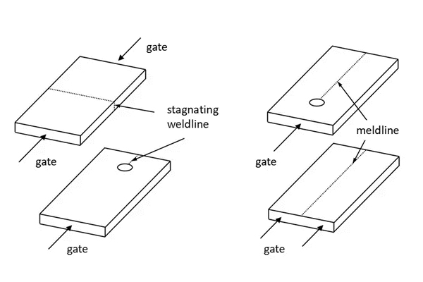
-
Q2026-04-27Hot Runner System in Plastic Injection Molds: Principles, Advantages, Applications, and Key Design COpen or CloseA
In plastic injection molding, mold design not only affects product appearance, but also directly impacts material utilization, production efficiency, dimensional stability, and overall cost control. Among the many mold technologies available, the Hot Runner System has become an essential solution for many mid-to-high-end products, precision components, and high-volume production projects.
Compared with traditional cold runner systems, the biggest advantage of a hot runner system is its ability to keep molten plastic in a molten state inside the runner channels and deliver it directly into the mold cavities. This significantly reduces runner waste while improving production efficiency and quality consistency. Its value is especially evident in applications involving expensive engineering materials, multi-cavity molds, automation, and products with demanding cosmetic requirements.
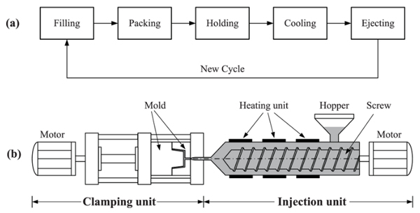
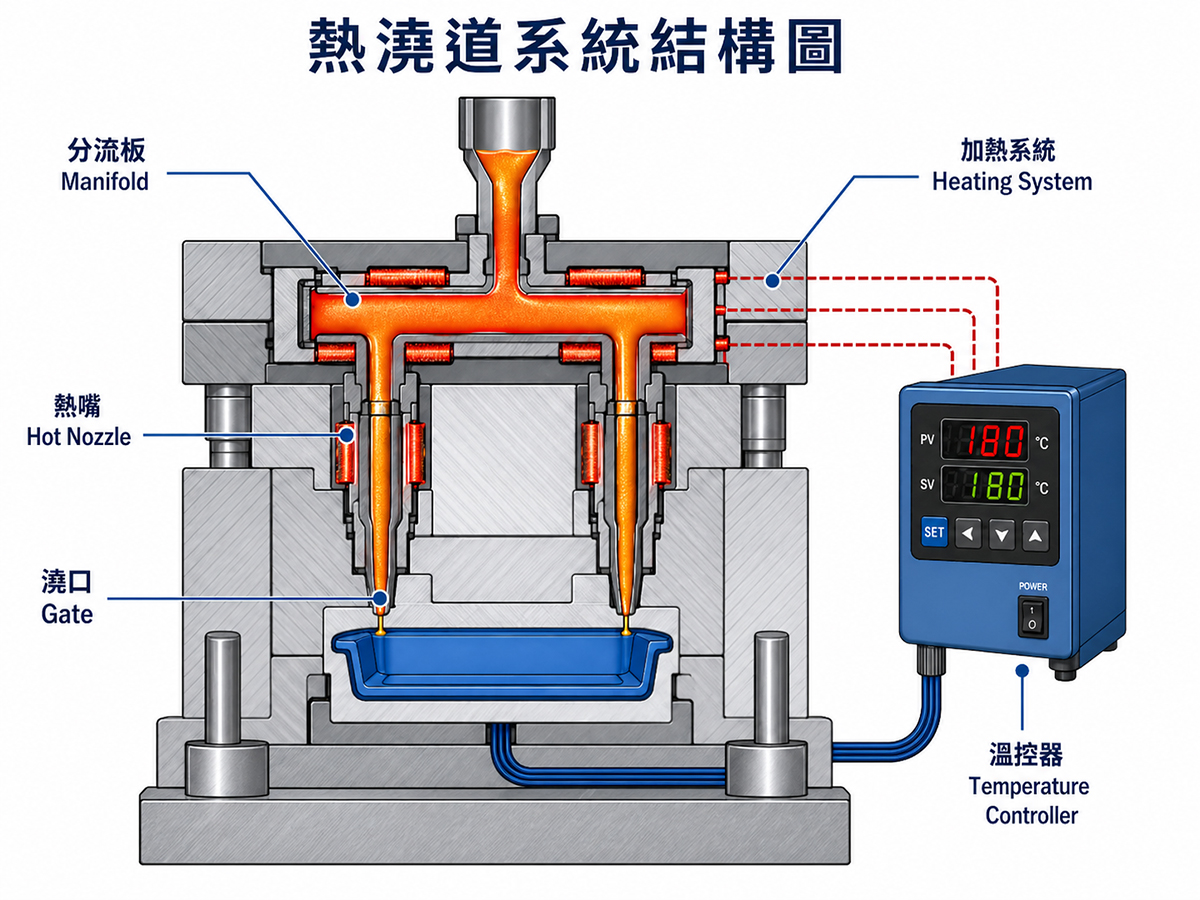
This article provides a complete overview of hot runner systems, covering their principles, structure, advantages, common challenges, suitable applications, and key considerations for mold development.1. What Is a Hot Runner System?
A hot runner system is a mold technology that uses heating elements to keep plastic material in a molten state within the runner system and deliver the melt directly into the product cavities.
In traditional cold runner molds, plastic in both the part and runner solidifies after each injection cycle, generating runner scrap that must be reground, recycled, or discarded. In contrast, a hot runner system keeps the runner continuously heated through controlled temperature zones, preventing the material from solidifying inside the runner and significantly reducing material waste and secondary processing.
In simple terms, the core value of a hot runner system is not only “runnerless molding,” but also achieving more controlled filling and molding through stable temperature control and melt flow management.2. Main Components of a Hot Runner System
- Manifold
The manifold distributes molten plastic from the injection machine to multiple gates or cavities.
For multi-cavity molds, manifold design is especially critical. Runner lengths, pressure losses, and flow balance must be carefully designed to ensure uniform filling in every cavity. - Hot Nozzle
The hot nozzle transfers molten resin from the manifold into the mold cavity.
Common nozzle types include:- Open Gate
- Valve Gate
- Heating System
Heating elements maintain the manifold and nozzles at controlled temperatures, preventing premature cooling of the resin inside the runner.
Heating stability directly influences material flow and part quality. - Temperature Controller
Temperature controllers regulate each heating zone, often independently controlling the manifold and nozzles.
Because different plastics respond differently to temperature, precise and stable temperature control is one of the most critical factors in hot runner performance.
3. Difference Between Hot Runner and Cold Runner Systems
The main difference lies in whether the plastic inside the runner solidifies after each molding cycle.
Cold Runner Advantages
- Simpler mold structure
- Lower initial mold investment
- Suitable for lower-volume or simpler products
Cold Runner Limitations
- Runner scrap generated every cycle
- Material waste
- Additional trimming and runner separation required
- Higher post-processing costs
Hot Runner Advantages
- Reduced material waste
- Shorter cycle time
- Higher production efficiency
- Improved part consistency
- Better cosmetic quality
Although hot runner molds generally involve higher technical complexity and upfront tooling costs, they often provide significant long-term advantages for high-volume and high-performance applications.
4. Key Advantages of Hot Runner Systems
- Reduced Material Waste
Because hot runners virtually eliminate cold runner scrap, they are particularly beneficial for expensive materials such as:- PC
- PA
- PBT
- PPS
- Higher Production Efficiency
Since runners do not need to cool and be removed after every cycle, cycle time can often be reduced, improving productivity. - Better Product Consistency
Stable temperature and flow control help reduce:- Dimensional variation
- Weight inconsistency
- Short shots
- Filling defects
- Better for Automation
Hot runner systems simplify automated part removal and integration with automated assembly or unmanned production lines. - Improved Cosmetic Quality
For products such as:- Cosmetic packaging
- 3C housings
- Consumer product exterior parts
5. Critical Design Considerations for Hot Runner Systems
A hot runner system is not simply a standard component added into a mold—it requires full engineering evaluation.
- Flow Balance
For multi-cavity molds, balanced filling is essential.
Poor balance may lead to:- Short shots
- Weight variation
- Dimensional instability
- Increased defect rates
- Thermal Uniformity
Uniform temperature control is critical.
Overheating may cause:- Material degradation
- Burning
- Color variation
- Poor flow
- Short shots
- Weld lines
- Material Characteristics
Different plastics behave differently in hot runner systems.
Considerations include:- Glass-filled material wear
- Carbon buildup with flame-retardant resins
- Residence time sensitivity for heat-sensitive materials
- Gate Type Selection
Gate design depends on product structure and appearance requirements.- High cosmetic demand → Valve Gate
- Cost-focused simple parts → Open Gate
- Maintenance Accessibility
Hot runner systems involve heaters, thermocouples, and multiple control zones.
Maintenance access should be considered during mold design to reduce downtime risks.
6. Common Hot Runner Challenges and Improvements
- Stringing
Possible causes:- Excessive nozzle temperature
- Low resin viscosity
- Poor gate shut-off
- Adjust temperature settings
- Optimize gate design
- Use valve gate nozzles
- Drooling
Molten resin leaking from the nozzle may cause contamination and instability.
Typical causes:- Poor nozzle design
- Excessive temperature
- Unstable melt control
- Material Degradation
Dead spots or long residence times may cause:- Black specks
- Burn marks
- Color variation
- Short Shots or Uneven Filling
Often related to:- Poor flow balance
- Unstable temperature control
- Excessive pressure loss
- Color Change or Material Residue
For transparent parts or frequent color changes, residual material inside the system may cause contamination or color inconsistency.
7. Products Suitable for Hot Runner Systems
Hot runner systems are often worth evaluating for products with:
- High annual production volumes
- Expensive plastic materials
- Multi-cavity mold requirements
- High cosmetic demands
- Automated production needs
- Goals to reduce runner waste and secondary processing costs
Typical applications include:
- Cosmetic packaging
- Electronic housings
- Precision mechanical parts
- Consumer product appearance components
- High-volume multi-cavity molded parts
8. CHII LEE’s Technical Strength in Hot Runner Mold Development
Implementing a hot runner system is not simply selecting components—it requires integrating mold design, material behavior, flow balance, temperature control, and mass production considerations.
Without proper early-stage planning, even a hot runner mold may fail to deliver its full benefits.
With decades of expertise in plastic mold design, mold manufacturing, and injection molding, CHII LEE provides one-stop support from product development and mold evaluation to tooling and mass production.Based on product structure, material properties, cosmetic requirements, and production volume, we help customers evaluate:
- Suitable hot runner configurations
- Gate system selection
- Mold design optimization
- Production-oriented engineering solutions
Our development approach focuses on:
- Hot runner layouts based on part geometry and cavity requirements
- Mold design optimization according to resin characteristics
- Balancing cosmetic quality, efficiency, and production stability
- Integrating tooling and molding know-how for consistent performance
- Evaluating total project cost, not just tooling price alone
For multi-cavity molds, precision parts, appearance components, and high-volume programs, hot runner selection is often not just a technical decision—but a critical factor affecting yield, productivity, and total cost.
9. Conclusion
The value of hot runner systems goes far beyond reducing runner waste.
They help improve:
- Product consistency
- Production efficiency
- Quality stability
- Overall manufacturing performance
For high-volume, high-requirement, or high-material-cost applications, hot runner systems are often a technology worth prioritizing.
However, whether a hot runner system is the right choice still depends on a comprehensive evaluation of:
- Product structure
- Material properties
- Number of cavities
- Cosmetic requirements
- Production scale
Only when mold design, material behavior, and process requirements are considered together at the early development stage can the full benefits of hot runner technology be realized.
10. Contact CHII LEE for Hot Runner Mold Evaluation
If you are planning a plastic mold development project or would like to evaluate whether a hot runner system is suitable for your product, feel free to contact CHII LEE.
Based on your product structure, material requirements, cosmetic expectations, and estimated production volume, we can help evaluate your project from both tooling and mass production perspectives, and provide a more suitable plastic injection molding solution. - Manifold
-
Q2026-05-14What Is a Cable Marker? A Complete Guide to C-Ring Wire Markers for Low-Voltage SystemsOpen or CloseA
Introduction
In modern buildings and facilities, low-voltage systems form the invisible backbone of daily operations — structured network cabling, CCTV surveillance, access control, intercom, public address (PA), and building automation all depend on dense runs of signal cables and control wiring. For system integrators, low-voltage contractors, and facility maintenance teams, the ability to quickly and accurately identify every individual cable is not a matter of preference — it is a professional necessity.
A cable marker, also known as a wire marker or cable identification ring, is the small but critical component that makes reliable cable identification possible. Among the various cable marking solutions available today, the C-ring cable marker has emerged as the preferred choice for low-voltage installation professionals, offering a unique combination of flexibility, durability, and ease of use that conventional markers simply cannot match.
What Is a Cable Marker?
A cable marker is an identification device designed to clip or attach onto individual wires or cables, displaying alphanumeric characters, symbols, or color codes for clear, permanent labeling. In low-voltage wiring environments — where network cables, signal lines, and control wires often share the same conduit or cable tray — unambiguous identification is essential. A misidentified cable during maintenance can result in system downtime, data loss, or equipment damage.
Cable markers are available in several formats: adhesive labels, heat-shrink sleeves, slide-on plastic ferrules, and clip-on ring markers. Of these, the C-ring cable marker stands out for its installation flexibility, long-term legibility, and suitability for the dense, space-constrained wiring environments common in low-voltage system installations.
C-Ring Cable Marker: Design and Mechanism
The C-ring wire marker takes its name from its open-profile cross-section, shaped like the letter "C." This open-ring design — manufactured from rigid engineering plastic — can be clipped directly onto a cable at any point along its length without the use of any tools, requiring only one hand to install.
This is a fundamental advantage over conventional soft-sleeve markers, which must be threaded onto the wire before termination. Once cables are terminated and routed in a distribution panel, network cabinet, or cable tray, traditional markers become impractical to install without first disconnecting the wire — a disruptive and time-consuming process. The C-ring eliminates this problem entirely, enabling cable labeling or re-labeling at any stage of the project lifecycle without interrupting system operation.
CHII LEE Enterprise, a Taichung-based plastic injection molding manufacturer with over 40 years of industry experience, produces the LT Series C-ring wire markers as a proprietary product line — engineered to meet the demanding performance requirements of professional low-voltage installations.
Core Material: POM Engineering Thermoplastic
The LT Series C-ring cable markers are manufactured from POM (Polyoxymethylene), a high-performance engineering thermoplastic widely used in precision industrial components. POM delivers a combination of mechanical and chemical properties that make it particularly well-suited for long-term cable marking applications:
- Operating Temperature Range: -20°C to +120°C (-4°F to +248°F): POM maintains dimensional stability and clamping force across a wide thermal range. Whether deployed in cold outdoor environments or in proximity to heat-generating equipment such as network switches, UPS systems, or motor control panels, the marker ring retains its shape and grip without deforming or loosening — ensuring reliable identification throughout the full service life of the installation.
- UV Resistance: Prolonged UV exposure is one of the most common causes of cable marker degradation in outdoor low-voltage installations — including outdoor CCTV, perimeter security cabling, and rooftop equipment wiring. Standard plastics become brittle, discolored, or cracked under continuous sunlight. POM's inherent UV resistance allows LT Series markers to withstand long-term outdoor exposure while maintaining structural integrity and print legibility.
- Chemical Resistance (Acid & Alkali): Cable markers in industrial facilities, food processing plants, and coastal environments are regularly exposed to cleaning agents, mild acids, alkaline solutions, and salt-laden air — all of which can degrade standard plastic markers over time. POM offers good resistance to a wide range of common chemicals, making LT Series C-rings a reliable choice for corrosive or high-humidity environments.
- High Rigidity with Sufficient Toughness: POM's mechanical profile — rigid enough to maintain a secure clip-on fit, yet tough enough to resist cracking under repeated installation and removal cycles — extends the working life of the marker ring and ensures consistent performance across thousands of labeling applications.
Key Features and Benefits
1. Hot-Stamped Legends: Scratch-Resistant, Fade-Proof, and Long-Term Legible
Legibility over the long term is the single most important performance criterion for any cable marker. Conventional soft-sleeve markers are prone to legend fogging — gradual degradation of printed characters caused by heat, humidity, or chemical contact — which renders the marking unreadable and creates serious maintenance risks.
CHII LEE's LT Series uses a hot-stamping process to permanently bond the legend onto the POM ring surface. Combined with POM's chemical stability, this process produces characters that remain crisp and legible in demanding environments. The adhesion strength of the hot-stamped legend has been verified through physical scratch testing — applying force with a blade across the character surface leaves the legend intact and undamaged — demonstrating scratch resistance that significantly exceeds conventional ink printing. Whether subject to abrasion during installation, long-term compression from cable tie bundling, or incidental contact during maintenance, the legend retains its clarity for the service life of the installation.
2. Pre- and Post-Termination Installation — One-Hand Operation
One of the most common challenges in low-voltage project work is discovering unlabeled cables after all terminations are complete and the system is live. Unlike heat-shrink sleeves or slide-on ferrules that must be applied before termination, C-ring markers can be installed or replaced at any time — even on active, live-terminated cables — without disconnecting any wiring. The single-hand clip-on mechanism enables fast labeling in confined spaces such as distribution boards, patch panels, and network racks, significantly reducing rework costs and eliminating system downtime during labeling operations.
3. Tool-Free Removal and Replacement
Re-labeling during system upgrades, zone reconfigurations, or cable management audits is straightforward: the open C-ring profile can be unclipped and removed by hand without cutting tools or destructive methods. This makes the LT Series markers genuinely reusable and minimizes disruption to surrounding cabling during maintenance operations.
4. Nine Sizes — Compatible with a Wide Range of Cable Diameters
The LT Series is available in nine sizes (models LT020 through LT030), accommodating cable diameters from fine signal wires to heavier control cables. This broad size range ensures a secure, correctly fitted marker across the full variety of cable types encountered in low-voltage system installations.
5. Color Coding and Custom Legends
The LT Series supports full alphanumeric character sets (A–Z, 0–9) and common symbols (+, −, /), available in multiple ring body colors for systematic color-coded cable management. Ordering is structured to suit both small-scale and large-scale project requirements:
- Standard models with existing character sets: MOQ 20 units — ideal for small-batch labeling, project top-ups, or maintenance stock
- Custom legends or special print specifications: MOQ 2000 units — for project-specific coding systems or branded installations
Applications in Low-Voltage Systems
The LT Series C-ring cable marker is engineered for the full range of low-voltage and extra-low-voltage (ELV) system applications:
- Structured Network Cabling (LAN/WAN) — Patch panels, horizontal cabling runs, and fiber optic terminations in data centers, server rooms, and enterprise networks require systematic labeling for efficient moves, adds, and changes (MACs)
- CCTV and Video Surveillance Systems — Clear differentiation between coaxial signal cables, IP camera network cables, and power supply wiring simplifies fault diagnosis and future system expansion
- Access Control and Intercom Systems — Multi-zone, multi-floor control wiring must be precisely identified to prevent mis-operation and ensure system integrity
- Public Address (PA) and Background Music Systems — Complex audio signal routing requires clear cable identification to reduce troubleshooting time during maintenance
- Building Automation Systems (BAS / BMS) — Sensor, actuator, and controller wiring in HVAC, lighting control, and energy management systems demands organized, identifiable cabling
- Fire Detection and Emergency Communication Systems — Regulatory compliance typically mandates clear cable identification; legible, durable markers support both installation inspection and emergency response
- Smart Home and Intelligent Building Low-Voltage Panels — Organized, labeled cabling simplifies future device additions, system integrations, and periodic maintenance
- Outdoor Security and Perimeter Cabling — UV resistance and wide operating temperature range ensure marking integrity for outdoor CCTV, access control readers, and perimeter detection systems
Manufacturing and Customization
CHII LEE Enterprise manufactures the LT Series C-ring cable markers using in-house plastic injection molding at its facility in Shengang District, Taichung, Taiwan. All tooling is produced internally, enabling direct control over quality, lead times, and product customization.
- Sample orders fulfilled within 15 working days
- Standard production orders (up to 10,000 units) shipped within 30 days
- Standard packaging: 20 units per box, 56 boxes per carton
- Standard models with existing character sets: MOQ 20 units
- Custom legends or special print specifications: MOQ 2000 units
Conclusion
Cable markers may be among the smallest components in a low-voltage installation, but their impact on long-term system maintainability, fault diagnosis efficiency, and operational safety is substantial. Low-voltage wiring environments — with their high cable density, diverse system types, and ongoing adds and changes — place particularly high demands on cable identification solutions.
The C-ring format addresses the core installation challenge: the ability to label or re-label cables at any stage, without disconnection. The use of POM engineering thermoplastic elevates performance to true industrial-grade standards — a service temperature range of -20°C to +120°C, UV resistance, chemical resistance, and a hot-stamped legend proven scratch-resistant through blade testing — ensuring that every labeled cable remains clearly identifiable throughout the full lifecycle of the installation.
For low-voltage contractors, system integrators, and facility management teams seeking a professional, reliable, and flexible cable marking solution, CHII LEE's LT Series C-Ring Wire Markers are the dependable choice.
*Learn more about CHII LEE's LT Series C-Ring Wire Markers at
[chiilee.com]: https://www.chiilee.com/en/wiring-marking-c-ring
E-mail (International): service@chiilee.com -
Q2026-05-21Mold Doctor Diagnosis ServiceOpen or CloseA
Senior technicians come to you · Any mold brand welcome · Diagnosis report within 30 minutes
Service Overview
Q: What is the “30-Minute Mold Doctor Diagnosis” service?
A: CHII-LEE’s senior technicians will travel directly to your factory or facility. By examining finished parts and mold conditions on-site, we identify the root cause of the problem and deliver concrete improvement recommendations — all within 30 minutes.
No need to transport your molds. We come to you.Q: What kinds of problems can be diagnosed?
A: Our diagnosis covers a wide range of common issues, including:- Part defects: Sink marks, flash, warpage, flow marks, short shots
- Mold defects: Ejection failure, wear and abrasion, galling, dimensional deviation, poor venting
- Process issues: Inconsistent cycle times, abnormal injection pressure, difficult demolding
Any quality or process issue related to plastic injection molding is welcome. Contact us to schedule a diagnosis.
Q: Are there geographic restrictions?
A: We are based in Shengang, Taichung, and primarily serve Taichung and the central Taiwan region. For inquiries outside this area, please contact us to discuss feasibility. Remote video diagnosis can also be arranged in advance.
Fees & Process
Q: Is the diagnosis service charged?
A: Please contact our sales team directly to confirm current service packages. We will recommend the most suitable arrangement based on your situation.Q: What is the process after booking?
- Book an Appointment: Contact us by phone or LINE to describe the issue and your location
- Confirm Schedule: Our team arranges a technician visit at a convenient time
- On-Site Diagnosis: The technician inspects the parts and mold, completing the diagnosis within 30 minutes
- Recommendations Delivered: We explain the root cause and provide improvement directions or a repair proposal
Common Questions
Q: Can you diagnose molds that weren’t made by Chee-Lee?Existing Customers
A: Absolutely. We provide diagnosis services regardless of which manufacturer made the mold.
Many clients come to us after their original supplier discontinued service or was unable to resolve the issue. This is one of the core values of our Mold Doctor service.Q: We don’t have an existing supplier relationship — can we book a diagnosis as a first step?New Customers
A: You are very welcome to. Many clients use the diagnosis service to evaluate Chee-Lee’s technical expertise and service quality before committing to a formal partnership.
Feel free to bring your current production issues or new product development requirements. We are happy to provide preliminary Design for Manufacturability (DFM) feedback as well.Q: Can a diagnosis really be completed in 30 minutes?
A: For most common injection molding problems, yes. Drawing on over 40 years of mold development experience, our technicians can identify the root cause within 30 minutes.
For more complex cases, we will explain the situation honestly on-site and arrange further in-depth analysis as needed. -
Q2026-05-23The Complete Guide to Cable MarkersOpen or CloseA
1. What Are Cable Markers?
Cable markers (also known as wire markers, cable labels, or cable identification tags) are essential components used to identify, organize, and manage cables and wires in electrical, networking, telecommunications, and industrial systems. Far more than simple labels, they are a critical part of any safe, compliant, and efficient installation — from small control panels and junction boxes to large-scale industrial facilities and data centers.
Proper cable marking ensures that every wire can be traced, identified, and maintained throughout the entire lifecycle of an installation — reducing errors, improving safety, and cutting maintenance costs.
2. What Are Cable Markers Used For?
2.1 Cable Identification & Traceability
The primary purpose of C-type cable markers is to give every wire a clear, readable identity. In environments where hundreds of cables run through conduits, cable trays, or distribution panels, wire markers allow technicians to instantly identify:
- Which circuit or system a cable belongs to
- Its voltage rating, function, or destination endpoint
- Phase, polarity, or signal type
Without proper cable identification, tracing a single wire through a complex installation can take hours. With clearly marked cables, the same task takes seconds — saving time and reducing costly downtime.
2.2 Electrical Safety & Hazard Prevention
Unmarked or poorly labeled cables present serious electrical safety risks. Cable markers help prevent:
- Accidental cutting of live or high-voltage wires
- Incorrect wiring connections during installation or repair
- Electrical faults caused by misrouted cables
- Confusion between similar-looking conductors in multi-core systems
Color-coded and alphanumeric cable markers make hazards immediately visible, protecting both workers and equipment — a key requirement in any industrial wiring or electrical installation project.
2.3 Maintenance, Troubleshooting & Reduced Downtime
When faults occur in electrical systems, downtime is costly. Comprehensive cable labeling enables maintenance teams to:
- Rapidly isolate the faulty circuit without guesswork
- Follow wiring routes without relying solely on documentation
- Hand off work between shifts or technicians with zero ambiguity
- Significantly reduce Mean Time to Repair (MTTR)
This is especially critical in 24/7 operations — manufacturing plants, data centers, utilities — where speed of response directly impacts productivity and revenue.
2.4 Regulatory Compliance & Quality Standards
Many industries mandate cable labeling under international standards and codes. Our products are manufactured under an ISO 9001 Quality Management System, which means every stage — from raw material sourcing and production to final inspection — is governed by rigorous quality controls and standardized processes.
Choosing an ISO 9001 certified cable marker supplier means:
- Consistent product quality across every batch and order
- Full traceability of materials and production processes
- Rigorous supplier management and incoming material verification
- A continuous improvement framework that drives ongoing product optimization
2.5 Streamlined Installation & Project Management
During the wiring phase of any project, cable markers keep large installation teams coordinated and efficient. Installers can:
- Pre-label cables before pulling them through conduits
- Verify correct routing at every junction point
- Avoid costly re-wiring mistakes early in the project lifecycle
The result is faster project completion, fewer errors from day one, and lower overall installation costs — making cable markers a high-ROI investment for any contractor or systems integrator.
3. Industrial vs. Low-Voltage Wire Markers: Key Differences
While they may look similar, industrial cable markers and low-voltage (structured cabling / weak current) wire markers are engineered for very different environments and performance requirements.
Industrial Cable Markers
Typical applications: Factory automation, heavy electrical panels, Motor Control Centers (MCC), substations, machine wiring
Property Specification Temperature Rating High-heat environments; typically rated 85°C–105°C or above Material High-performance PVC, nylon (PA), or polyolefin compounds Chemical Resistance Resistant to oils, solvents, industrial cleaners, and hydraulic fluids Mechanical Strength Abrasion-resistant, tear-resistant; strong retention force Cable Diameter Range Larger gauges — typically 1.5mm² to 25mm² and above Marking Type Sleeve, heat-shrink tubing, clip-on markers Text Size Larger font for fast visual identification in noisy environments Low-Voltage / Structured Cabling Wire Markers
Typical applications: Network cabling, telephone systems, CCTV/security, access control, fire alarm signal cables, structured wiring
Property Specification Temperature Rating Standard indoor environments; typically 60°C–70°C is sufficient Material POM, nylon, or soft self-adhesive materials for flexible application Chemical Resistance Lower requirement; primarily moisture and dust resistance Mechanical Strength Lower requirement; emphasis on lightweight and ease of installation Cable Diameter Range Smaller gauges — typically 0.95mm² to 6.65mm² Marking Type Self-adhesive labels, flag markers, sleeve markers, C-type Ring Text Size Smaller, high-precision font for densely packed fine conductors Side-by-Side Comparison
Criteria Industrial Wire Markers Low-Voltage Wire Markers Environment Harsh, high-temp, chemical exposure Indoor, relatively mild Cable Gauge Heavy (high current) Fine (low-voltage signals) Material Grade High weatherability & strength Lightweight & flexible Installation Method Sleeve, heat-shrink, clip-on Self-adhesive, flag, sleeve Standards IEC, UL, CE TIA/EIA, ISO/IEC 11801 Price Range Higher More economical Buyer's Guide: Which Type Do You Need?
- Distribution panels, motors, heavy electrical equipment → Choose industrial-grade; prioritize thermal and chemical resistance
- Network rooms, CCTV, access control, low-voltage panels → Choose structured cabling markers; prioritize clarity and installation speed
- Light industrial facilities with mixed low-voltage systems → Recommend industrial-grade spec for greater safety margin
4. Our C-type Cable Marker Product Advantages
- Durability & Harsh Environment Resistance:
Our C-type cable markers are engineered to perform in the most demanding conditions — resistant to high temperatures, UV exposure, chemicals, moisture, and mechanical abrasion. Whether installed in outdoor substations, heavy industrial machinery, or marine environments, our markers remain clearly legible and firmly secured throughout the full installation lifetime. - Wide Product Range & Comprehensive Specifications:
We offer a complete product portfolio covering every application — from AWG9-8 to AWG28-26. Whatever the cable diameter, installation environment, or identification system, we have the right solution for the job. - Easy Installation & Labor Cost Savings:
Our C-type cable markers are designed for fast and efficient cable identification in telecom, data center, and industrial applications. Featuring a one-handed C-ring snap-on design, they require no pre-cut sleeves, adhesive labels, or installation tools — helping reduce installation time, improve maintenance efficiency, and lower overall project labor costs. - ISO 9001 Certified Quality Management:
All our products are manufactured under ISO 9001 Quality Management System certification. From raw material procurement and process control to finished goods inspection, every step is governed by strict quality standards. This means every batch you receive delivers consistent, reliable performance — giving you confidence in project handovers, client acceptance, and long-term system reliability.
5. Material Evolution: Why the Industry Is Moving from PVC to POM & Nylon
Why PVC Is Losing Ground
For decades, PVC (polyvinyl chloride) was the dominant material for cable markers due to its low cost and ease of processing. However, as global environmental regulations have tightened, PVC use has come under increasing scrutiny and restriction:
- Halogen content:
PVC contains chlorine (a halogen) and releases toxic hydrogen chloride (HCl) gas when burned — a serious hazard to human health and the environment - EU RoHS & REACH regulations:
The European Union explicitly restricts halogenated materials in electrical and electronic equipment; PVC is increasingly listed as a substance requiring substitution in export products - Smoke toxicity in fires:
PVC combustion generates dense, highly toxic smoke that endangers evacuation personnel and firefighters - Difficult end-of-life disposal:
PVC is difficult to recycle; landfill or incineration both generate significant environmental pollution - Plasticizer concerns:
Traditional PVC requires plasticizers (such as phthalates) to maintain flexibility — some of which are classified as endocrine disruptors with potential health risks
Why POM & Nylon Are the New Standard
In response to PVC's limitations, the industry has shifted toward POM (polyoxymethylene / acetal) and Nylon (Polyamide, PA) as the preferred materials for modern cable markers:
Property POM (Polyoxymethylene) Nylon (Polyamide / PA) Environmental Compliance Halogen-free; RoHS & REACH compliant Halogen-free; RoHS & REACH compliant Temperature Range -40°C to 120°C -40°C to 150°C (grade dependent) Mechanical Strength High hardness; excellent dimensional stability High toughness; impact-resistant; crack-resistant Chemical Resistance Resistant to oils and solvents Resistant to oils and alkalis; partial acid resistance Combustion Characteristics Low smoke, low toxicity Low smoke, low toxicity; flame-retardant grades available Processability Excellent precision molding Easy to color; adjustable hardness grades Best Applications Industrial automation, precision wiring Heavy electrical, low-voltage, outdoor harsh environments What This Shift Means for Your Projects
This material transition is not just a regulatory compliance exercise — it reflects the entire industry's move toward sustainable, high-performance engineering. Specifying POM or nylon cable markers for your projects means:
- Meeting environmental export requirements for EU, Japan, Taiwan, and other major markets
- Providing higher fire safety assurance on construction sites and in completed installations
- Supporting your organization's ESG commitments and green procurement policies
- Benefiting from longer service life and more stable physical performance over time
Our product range has fully embraced this shift. We supply halogen-free POM and nylon cable markers that meet modern environmental standards without compromising on performance — giving you a solution that satisfies both today's regulations and tomorrow's sustainability requirements.
Conclusion
Cable markers may seem like a minor detail in any electrical or wiring project, but their impact on safety, efficiency, and long-term system reliability is significant. From basic wire identification to regulatory compliance, fast maintenance, and sustainable material choices — cable markers are an indispensable foundation of modern electrical infrastructure.
The industry's shift from PVC to POM and nylon also reflects a broader commitment: engineers, procurement managers, and contractors are increasingly choosing materials that perform better and align with global environmental standards. It is not just about compliance — it is about building systems that are safer, more durable, and more responsible.We believe every great cable marking solution must deliver on four core values:
Core Value What It Means in Practice Safety Clear identification eliminates miswiring and accidental cuts — protecting people and equipment Efficiency Fast installation and easy identification cut labor time across installation and maintenance Durability Resistance to heat, chemicals, and harsh environments ensures lifetime performance Sustainability Halogen-free materials support green procurement and ESG goals As an ISO 9001 certified manufacturer, we supply a complete range of industrial and low-voltage cable markers — backed by strict quality management, diverse specifications, and deep application expertise. We are committed to being your trusted, long-term partner for cable identification solutions.
One small marker. One safer, better-organized system.
Choosing the right cable marker is choosing a commitment to quality. -
Q2026-05-28Cable Labeling Standards — Frequently Asked Questions (FAQ)Open or CloseA
Q1. What is a cable labeling standard and why does it matter?
A cable labeling standard is a set of technical guidelines that define how cables should be identified, what information labels must carry, and where labels should be placed. Proper cable labeling helps to:
- Reduce troubleshooting time during faults
- Prevent misoperation that could cause system downtime
- Meet project inspection requirements
- Improve efficiency for future maintenance and system expansion
Q2. What do the main international cable labeling standards specify?
The most widely referenced standards in the industry span three domains: IT/telecom, electrical, and industrial cabling:
- ANSI/TIA-606 (Administration Standard for Telecommunications Infrastructure):
defines identifier formats for cables, ports, spaces, and pathways. It requires each cable to carry a unique identifier, mandates labeling at both cable ends and all intermediate access points, and requires complete installation records to be maintained. - ISO/IEC 14763-2 (Implementation and Operation of Customer Premises Cabling):
specifies that cables, patch panels, and ports must all be clearly identified, and that the labeling system must remain consistent with as-built drawings throughout the facility's lifecycle. - IEC 60445 (Identification of Equipment Terminals and Conductors):
requires electrical conductors and terminals to be identified by color coding or alphanumeric markings. Conductors of different potentials or functions must use corresponding colors to prevent wiring errors. - NFPA 70/NEC (National Electrical Code):
requires conductors to be identified by color or labeling, with specific identification obligations for large-gauge conductors and multi-circuit systems, ensuring maintenance personnel can correctly identify energized conductors. - UL 969 (Standard for Marking and Labeling Systems):
specifies that label materials must demonstrate sufficient adhesion, heat resistance, moisture resistance, and abrasion resistance to remain clearly legible under various environmental conditions over the long term. - TIA-568 (Commercial Building Telecommunications Cabling Standard):
defines the overall architecture of structured cabling systems and requires end-to-end identification throughout the cabling system, with both the origin and destination of each circuit clearly marked.
Q3. What information should a standard cable label include?
Per ANSI/TIA-606, a complete cable label should contain at minimum:
- Unique cable identifier (e.g., C-01-A)
- Origin (source rack/patch panel number)
- Destination (termination port)
- Cable type (e.g., CAT6, fiber, coaxial)
- Installation date (for maintenance reference)
Labels must be applied at both ends of the cable and at all intermediate access points (patch panels, junction boxes).
Q4. What cable identification products does CHII LEE/CHII LII offer?
We specialize in manufacturing C-type Ring Cable Markers — an open-ring design that clips directly onto the cable from the side, with no need to thread from the cable end.
Unlike some Clip-on Cable Markers on the market that rely on barb or hook structures to grip the cable, our C-type Ring Cable Markers are barb-free. Installation uses a guided rail-like mechanism: pushing the ring forward causes the opening to naturally splay open and glide smoothly onto the cable, with no clamping force applied to the cable jacket — meaning no scratching or damage to the cable surface.
When a marker needs to be replaced or removed, it can be detached by hand and a new one snapped on in its place — no tools required, no harm to the cable. This makes maintenance fast and practical, even in high-density wiring environments.All products are manufactured from POM (Polyoxymethylene) engineering-grade thermoplastic, offering the following material advantages:
Property Description High Rigidity Dimensionally stable — markers retain their shape over time Excellent Wear Resistance Suitable for environments with frequent cable movement or reinstallation Chemical Resistance Resistant to oils, solvents, and common industrial chemicals Low Friction Coefficient Allows smooth installation without damaging the cable jacket Wide Operating Temperature Range Stable performance from -20°C to +100°C Excellent Electrical Insulation Complies with electrical wiring safety requirements Q5. How do I select the correct C-type Ring Cable Marker size?
C-type Ring Cable Markers must be selected based on the cable's actual outer diameter (OD), not the conductor diameter.
Please refer to the standard specification table below (dimensions in mm):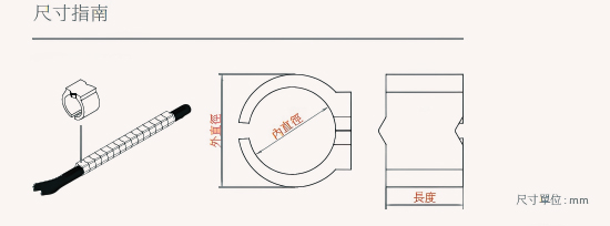
Model Wire Gauge Length (mm) Inner Diameter (mm) Outer Diameter (mm) Compatible Cable LT-020 AWG 28–26 2.4 0.95 1.90 Single-core fiber cable LT-021 AWG 24–22 3.0 1.65 2.80 Single-core fiber cable LT-022 AWG 22–20 3.0 2.05 3.40 2-core fiber cable LT-023 AWG 18–16 3.0 2.525 4.00 Dual-core fiber cable LT-024 AWG 16–14 3.0 3.25 4.60 Dual-core fiber cable, indoor telephone cable LT-025 AWG 14–12 3.0 3.65 5.20 Indoor telephone cable LT-026 AWG 12–10 3.0 4.20 6.00 CAT5 cable LT-028 AWG 10–9 5.0 5.90 7.70 CAT6/CAT7/CAT8 cable LT-030 AWG 9–8 5.9 6.65 8.80 CAT8 cable, corrugated flexible conduit, 5C coaxial cable
Selection Guidelines
- Choose a marker with an inner diameter (ID) slightly larger than the cable's OD
- Avoid too tight (difficult to thread) or too loose (marker slides)
- Cross-check both AWG gauge and the compatible cable type column to confirm fit
Q6. What is the significance of color coding?
Each C-type Ring Cable Marker model is assigned a distinct color corresponding to a specific AWG wire gauge range, consistent with the IEC 60445 color identification principle.
Benefits of Color Coding
- Allows technicians to visually confirm the correct marker size at a glance during installation
- Reduces the risk of selecting the wrong marker in high-density wiring environments
- Creates a dual-identification system combining color and printed text
Q7. What is the standard color, and do you offer customization?
- Standard Specification
All C-type Ring Cable Marker models are supplied in white with black text as standard, providing clear contrast for writing or printing cable identification information — suitable for the majority of installation environments. - Custom Ring Color Service
For projects with specific color-coding requirements, we offer a custom ring color service across all models. Whether you need colors differentiated by system zone, voltage level, or cable type, we can produce markers in specified colors to support a more intuitive visual identification system on-site.
For custom color quotations or samples, please contact CHII LEE/CHII LII sales team.
For further product selection assistance, please contact CHII LEE/CHII LII technical support team.